Heat pipe intercooling system for a turbomachine

A technology of turbine and heat pipe, applied in turbine/propulsion fuel delivery system, fuel heating of turbine/propulsion unit, charging system, etc., can solve a large number of infrastructure and capital costs and other issues

Inactive Publication Date: 2016-10-26
GENERAL ELECTRIC CO
View PDF4 Cites 0 Cited by
  • Summary
  • Abstract
  • Description
  • Claims
  • Application Information

AI Technical Summary

Problems solved by technology

However, conventional intercoolers are large systems requiring significant infrastructure and capital costs

Method used


Image

  • Heat pipe intercooling system for a turbomachine
  • Heat pipe intercooling system for a turbomachine
  • Heat pipe intercooling system for a turbomachine

Examples


Embodiment Construction

[0113] One or more specific aspects / embodiments of the invention are described below. In an effort to provide a concise description of these aspects / embodiments, not all features of an actual implementation may be described in the specification. It should be recognized that in the development of any such actual implementation, as in any engineering or design project, many implementation-specific decisions must be made to achieve the developer's specific goals, such as compliance with machine-related, System-related and business-related constraints, which may vary from one implementation to another. It should be appreciated, however, that such a development effort might be complex and time consuming, but would nonetheless be a routine undertaking of design, fabrication, and production for those of ordinary skill having the benefit of this disclosure.

[0114] When introducing elements of various embodiments of the invention, the articles "a," "an," and "the" are intended to me...


PUM


Abstract

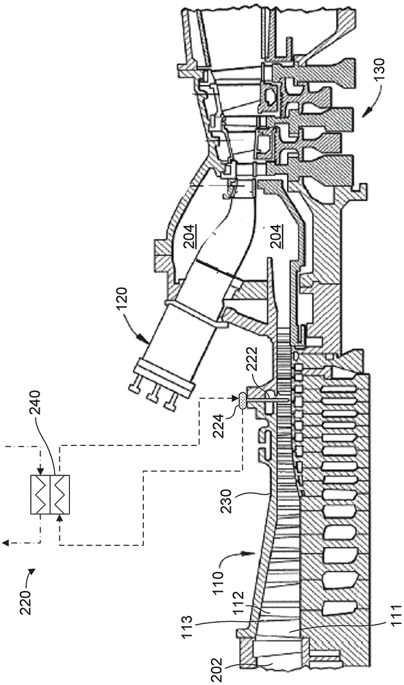
A turbomachine includes a compressor including an intake portion and an outlet portion. The compressor compresses air received at the intake portion to form a compressed airflow that exits into the outlet portion. A combustor is operably connected with the compressor, and the combustor receives the compressed airflow. A turbine is operably connected with the combustor. The turbine receives combustion gas flow from the combustor. An intercooler is operatively connected to the compressor, and at least a portion of the intercooler is placed in an inter-stage gap between rotor blades and stator vanes of the compressor. The intercooler has a plurality of heat pipes that extend into the inter-stage gap. The plurality of heat pipes is operatively connected to one or more manifolds. The plurality of heat pipes and the one or more manifolds are configured to transfer heat from the compressed airflow to a plurality of heat exchangers.

Description

technical field [0001] Exemplary embodiments of the invention relate to the field of turbomachines, and more particularly, to heat pipe intercoolers for turbomachines. Background technique [0002] A turbine includes a compressor operatively connected to a turbine, which in turn drives another machine, such as an electrical generator. The compressor compresses an incoming air stream, which is delivered to the combustor to be mixed with fuel and ignited to form high temperature and high pressure combustion products. The high temperature and high pressure combustion products are used to drive the turbine. In some cases, the compressed air stream exiting the compressor is recompressed to achieve a certain combustion efficiency. However, recompressing the compressed air stream raises the temperature of the air stream above desired limits. Therefore, the air flow is passed through an intercooler before being compressed again. An intercooler between two compressor stages reduc...

Claims


Application Information

Patent Timeline
Patent Type & Authority Applications(China)
IPC IPC(8): F02C7/143F02C7/224F01K23/04
CPCF01K23/04F02C7/143F02C7/224F05D2260/208F05D2260/211F05D2260/213F02C6/18Y02E20/16F01K23/02F02C7/141
Inventor S.埃卡纳亚克A.I.西皮奥J.P.里佐
Owner GENERAL ELECTRIC CO
Why Eureka
Try Eureka