Vertical annularly mounted efficient excitating fixed blade axial-flow type hydrogenerator and work doing method thereof

A hydroelectric generator, axial flow technology, applied in hydroelectric power generation, engine function, reaction engine, etc., can solve the problem of poor cooling effect of cooling system, low utilization efficiency of excitation magnetic field, large force on transmission shaft and bearing, etc. problems, to avoid bearing friction and energy consumption, simplify structure and materials, and achieve the effect of heat dissipation rate block

Inactive Publication Date: 2016-10-26
郭远军
View PDF0 Cites 0 Cited by
  • Summary
  • Abstract
  • Description
  • Claims
  • Application Information

AI Technical Summary

Problems solved by technology

[0007] The technical problems to be solved by the present invention are as follows: 1) The transmission shaft and bearing in the existing hydroelectric power generation device have relatively large losses due to the large force and high temperature generated by friction; 2) the generator of the existing hydroelectric power generation device Exciters and exciters will generate a lot of waste heat during work, and a special cooling system needs to be installed, and the cooling effect of the cooling system is not good, and it is easy to burn the core; 3) The high stable efficiency of the existing water turbine is only about 90%; 4) The existing hydro-generators are all customized machines for different terrains, and there are large differences in volume, which cannot be mass-produced; High strength requirements; 6) Low utilization efficiency of excitation magnetic field

Method used


Image

  • Vertical annularly mounted efficient excitating fixed blade axial-flow type hydrogenerator and work doing method thereof
  • Vertical annularly mounted efficient excitating fixed blade axial-flow type hydrogenerator and work doing method thereof
  • Vertical annularly mounted efficient excitating fixed blade axial-flow type hydrogenerator and work doing method thereof

Examples


Embodiment Construction

[0032]The following will clearly and completely describe the technical solutions in the embodiments of the present invention with reference to the accompanying drawings in the embodiments of the present invention; obviously, the described embodiments are only some, not all, embodiments of the present invention. Based on the embodiments of the present invention, all other embodiments obtained by persons of ordinary skill in the art without making creative efforts belong to the protection scope of the present invention.

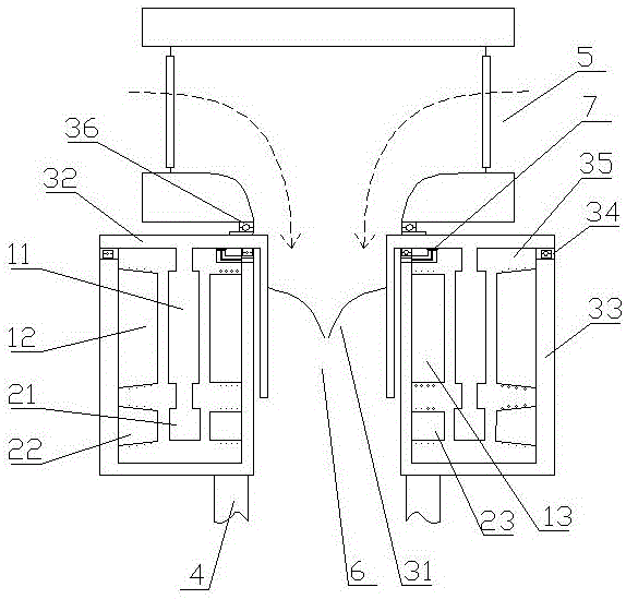
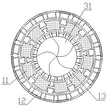
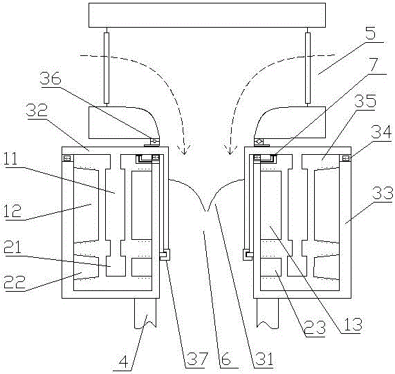
[0033] Option 1 (if figure 1 and figure 2 shown): a vertical ring-mounted high-efficiency excitation fixed-blade axial-flow hydroelectric generator, including a power generation mechanism 1, an excitation mechanism 2, a runner mechanism 3, a draft tube 4, a guiding mechanism 5 and a runner chamber 6; The wheel mechanism 3 includes rotating blades 31, an annular rotating cover 32 and an annular fixed cover 33. The rotating blades 31 are fan-shaped distributed ...


PUM


Abstract

The invention discloses a vertical annularly mounted efficient excitating fixed blade axial-flow type hydrogenerator and a work doing method thereof. The vertical annularly mounted efficient excitating fixed blade axial-flow type hydrogenerator comprises a power generation mechanism, an excitating mechanism, a runner mechanism, a draft pipe, a water guide mechanism and a runner chamber, wherein the runner mechanism comprises rotary blades, an annular rotary hood and an annular fixed hood; the rotary blades are distributed inside the annular rotary hood in a fan shape; the annular rotary hood and the annular fixed hood are coaxially connected through a sealing bearing to form a closed annular cavity; the power generation mechanism and the excitating mechanism are coaxially mounted in the annular cavity in parallel up and down; and the water guide mechanism, the runner chamber and the draft pipe form a water flow closed channel. The vertical annularly mounted efficient excitating fixed blade axial-flow type hydrogenerator disclosed by the invention is long in service life, relatively low in construction cost and production management cost and high in hydroenergy conversion efficiency.

Description

technical field [0001] The invention relates to the field of hydropower equipment, in particular to a vertical ring-mounted high-efficiency excitation fixed-blade axial-flow hydroelectric generator and a work method thereof. Background technique [0002] According to the working principle, hydroelectric power generation devices can be divided into two categories: impact turbines and impact turbines. The runner of the impact turbine is impacted by the water flow and rotates, and the pressure of the water flow remains unchanged during the working process, mainly due to the conversion of kinetic energy; the runner of the impact turbine is rotated by the reaction force of the water flow, and the pressure of the water flow during the working process Both energy and kinetic energy are changed, but mainly the conversion of pressure energy. [0003] Pelton turbines, because only part of the working wheels pass through the water, and part of the water bucket is under force, so the r...

Claims


Application Information

Patent Timeline
IPC IPC(8): F03B13/00F03B3/04F03B3/12F03B11/06H02K7/18H02K7/20H02K9/19
CPCF03B3/04F03B3/12F03B11/06F03B13/00F05B2220/7064F05B2220/7066F05B2260/20F05B2280/40H02K7/1823H02K7/20H02K9/19Y02E10/20Y02P70/50
Inventor 郭远军
Owner 郭远军
Why Eureka
Try Eureka