Low-nitrogen combustion technique based on circulating fluidized bed boiler

A circulating fluidized bed, low-nitrogen combustion technology, applied in the field of boiler combustion, can solve the problems of affecting the full combustion of fuel in the boiler, the reduction of boiler combustion efficiency, and the full combustion of unfavorable fuels, etc. Long time, the effect of reducing the generation of NOx

Active Publication Date: 2016-10-26
QINGDAO JINTIAN THERMAL POWER CO LTD
View PDF7 Cites 11 Cited by
  • Summary
  • Abstract
  • Description
  • Claims
  • Application Information

AI Technical Summary

Problems solved by technology

The circulating fluidized bed boiler has the remarkable characteristics of low nitrogen oxide emissions. The main reason is that the combustion temperature is low, only 850-1000 ℃, so the thermal NO x The second is that the solid bed material in the furnace has a great influence on NO along the height of the furnace. x The third is that circulating fluidized bed boilers are generally designed in a graded air supply mode, so that the dense phase area is in a reducing atmosphere, but although the traditional layout of secondary air inlet ducts can meet the requirements of the boiler for secondary air volume, However, the disturbance effect of the secondary

Method used


Image

  • Low-nitrogen combustion technique based on circulating fluidized bed boiler
  • Low-nitrogen combustion technique based on circulating fluidized bed boiler
  • Low-nitrogen combustion technique based on circulating fluidized bed boiler

Examples


Example Embodiment

[0036] The present invention will be further described in detail below in conjunction with the drawings and specific embodiments.

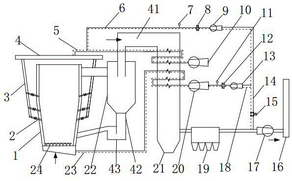
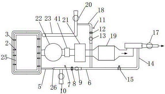
[0037] As shown in the figure, a low-nitrogen combustion process based on a circulating fluidized bed boiler. The circulating fluidized bed boiler includes a boiler 1, a cyclone separator 22, a dust collector 19, an induced draft fan 17 and a smoke stack 16, which are sequentially connected. The four walls of the inner wall of the boiler 1 are provided with water-cooled walls 25 with relief pipes. The relief pipes include single-hole relief pipes and double-hole relief pipes. The upper part of the boiler 1 is the dilute phase oxidation zone and the lower part is the dense-phase reduction zone. The bottom is provided with a water-cooled air distribution plate 24 for distributing the primary air. The outlet of the boiler 1 is connected to the inlet of the cyclone separator 22. The cyclone separator 22 is connected to the dense phase reduction zone of th...


PUM

PropertyMeasurementUnit
Granularityaaaaaaaaaa

Abstract

The invention discloses a low-nitrogen combustion technique based on circulating fluidized bed boiler. The circulating fluidized bed boiler comprises a boiler body, a cyclone separator, a deduster, an induced draft fan, a primary air supply system and a secondary air supply system which are connected in sequence. A smoke recirculation pipe is drawn out behind the induced draft fan. The primary air supply system and the secondary air supply system are connected to the smoke recirculation pipe in parallel. A burn-out chamber is arranged at an outlet of the cyclone separator. The low-nitrogen combustion technique based on the circulating fluidized bed boiler comprises the following steps that pulverized coal enters the boiler body under the action of primary air, specifically, the amount of smoke recirculation air in the primary air accounts for 8-10% the total air amount of the primary amount, and the amount of the primary air accounts for 40-45% of the total air amount; secondary air is introduced into the boiler body through the secondary air supply system, specifically, the amount of smoke recirculation air in the secondary air accounts for 12-14% the total air amount of the secondary air; fine flying ash enters the burn-out chamber; and over fire air is introduced into the burn-out chamber. According to the low-nitrogen combustion technique based on the circulating fluidized bed boiler, the burn-out chamber is arranged at the outlet of the separator, and part of smoke is mixed into the primary air and the secondary air, so that generation of NOx is reduced.

Description

technical field [0001] The invention belongs to the technical field of boiler combustion, and in particular relates to a low-nitrogen combustion process based on a circulating fluidized bed boiler. Background technique [0002] In the nitrogen oxides produced during boiler combustion, NO accounts for more than 90%, and nitrogen dioxide accounts for 5%-10%. The production mechanism is generally divided into the following three types: (1) Thermal type: During combustion, nitrogen in the air is Oxidation, with the increase of the reaction temperature T, the reaction rate follows an exponential law. When T<1500°C, the amount of NO produced is very small, and when T>1500°C, the reaction rate increases for every 100°C increase in T. 6-7 times larger; (2) Instantaneous reaction type: CH free radicals generated by pyrolysis of hydrocarbons in fuel volatiles can react with nitrogen in the air to form HCN and N, and then react with oxygen to form at an extremely fast speed. I...

Claims


Application Information

Patent Timeline
IPC IPC(8): F23C10/00F23C10/20F23C10/18F23C10/28
CPCF23C10/00F23C10/18F23C10/20F23C10/28F23C2202/30F23C2206/102
Inventor 董爱君姜玉旭张式雷李兴全徐夕仁崔秀宝梁法志李兆春张川云于祥红杨建国
Owner QINGDAO JINTIAN THERMAL POWER CO LTD
Why Eureka
Try Eureka