Mini-type constant temperature and humidity control device and temperature and humidity control method thereof

A temperature and humidity control, constant temperature and humidity technology, which is applied in household refrigeration devices, heating and ventilation control systems, and control inputs involving air characteristics, etc., can solve the problems of low temperature and humidity control accuracy, large vibration and interference, and cooling capacity of refrigeration devices mutation and other problems, to avoid electrical interference and mechanical vibration, to solve the effect of uncontrollable humidity and precise humidity control

Inactive Publication Date: 2016-10-26
JINAN HAINATE TECH
View PDF6 Cites 10 Cited by
  • Summary
  • Abstract
  • Description
  • Claims
  • Application Information

AI Technical Summary

Problems solved by technology

At present, in the field of constant temperature and humidity testing, there are mostly large-scale constant temperature and humidity chambers, walk-in constant temperature and humidity chambers and other testing equipment. Most of the cabins have a volume of more than 100L. The refrigeration system is mostly carried out by compressor Freon heat exchange, and the equipment is large. , high energy consumption, large vibration and interference during the start and stop of the compressor, which will affect the detection data of the equipment in the cabin
These large-capacity test chambers in the prior art are not suitable for testing small test samples due to their large capacity and relatively low temperature and humidity control accuracy.
In the prior art, there are also small and micro-sized test chambers with a volume of 20L or less. The temperature control of these test chambers is currently the commonly used control method of cooling and heating, and the temperature set by the user is achieved through PID control. value, but the cooling method of these test chambers is to use compressor refrigeration, the compressor is large in size, and the pipeline is complicated. The condenser and evaporator interception device in the refrigeration system are indispensable. On the other hand, there is a certain hysteresis in the start and stop of the compressor and it cannot be started frequently. However, the temperature and heat capacity in the micro-miniature test chamber are small, and the cooling capacity will suddenly change during the start and stop of the refrigeration device, which is easy to produce The phenomenon of temperature overshoot; in addition, the humidity control of the micro test chamber is currently aimed at the test chamber below 20L. Due to the volume limit, the traditional humidification, dehumidification and humidity control method cannot be used. Therefore, the micro test chamber below 20L in the prior art None of the small test chambers have humidity control
Due to the above reasons, the temperature and humidity control accuracy of the small test cabins in the prior art, especially the micro-miniature test cabins, is low, which cannot meet the requirements of a high-precision experimental environment, and affects the accuracy of the test data of the equipment in the cabin.

Method used


Image

  • Mini-type constant temperature and humidity control device and temperature and humidity control method thereof

Examples


Embodiment Construction

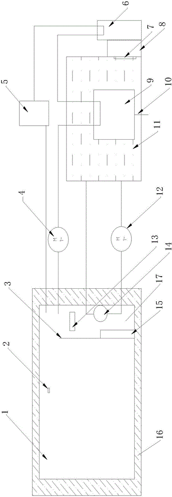
[0013] The present invention will be further described below in conjunction with accompanying drawing by non-limiting embodiment:

[0014] As shown in the accompanying drawings, a miniature constant temperature and humidity control device includes a test cabin 1 and a temperature and humidity control device. The test cabin 1 is a miniature cabin, and its internal volume is usually 1-20L. The internal size of the test cabin in this embodiment is: 300mm*300mm*320mm. The test cabin body 1 is provided with an insulating layer 16, and the insulating layer 16 is formed by polyurethane foaming process. The temperature and humidity control device mainly includes a condensed water tank 11, a condensing heat exchanger 9, a semiconductor cooling fin 7, a semiconductor cooling radiator 8, a heating heat exchanger 6, a finned radiator 14, a heating device 13, and an ultrasonic humidifier 5 . Wherein, the condensed water tank 11 is arranged on the outside of the test cabin body 1. During ...


PUM


Abstract

The invention discloses a mini-type constant temperature and humidity control device and a temperature and humidity control method thereof. The mini-type constant temperature and humidity control device comprises a test cabin and a temperature and humidity control device. The temperature and humidity control device comprises a condensation water tank, a condensation heat exchanger, a semiconductor refrigeration piece, a semiconductor refrigeration cooler, a temperature rise heat exchanger, a fin type cooler, a heating device and an ultrasonic humidifier. The condensation water tank is arranged outside the test cabin. The condensation heat exchanger is arranged in the condensation water tank. The semiconductor refrigeration piece is arranged in the condensation water tank. The semiconductor refrigeration cooler is arranged on the outer side wall of the condensation water tank. The temperature rise heat exchanger is arranged on the rear portion of the semiconductor refrigeration cooler. The heating device and the fin type cooler are both arranged in the test cabin. The fin type cooler is connected with the condensation water tank through a circulation water pump and a connection pipeline so as to form a circulation water way. The test cabin forms a circulation gas way through a circulation gas pump and a connection pipeline. The circulation gas way sequentially passes through the circulation gas pump, the condensation heat exchanger, the temperature rise heat exchanger and the ultrasonic humidifier to enter the test cabin.

Description

technical field [0001] The invention relates to a constant temperature and humidity control device, in particular to a miniature constant temperature and humidity control device. The invention also relates to the temperature and humidity control method of the miniature constant temperature and humidity control device. Background technique [0002] A large part of microelectronics and materials testing requires a constant temperature and humidity experimental environment to maintain the set temperature and humidity within a certain range and maintain the corresponding accuracy. For example, in the field of friction and wear testing, with the miniaturization of test samples, the The temperature and humidity control in a small range puts forward requirements. At present, in the field of constant temperature and humidity testing, there are mostly large-scale constant temperature and humidity chambers, walk-in constant temperature and humidity chambers and other testing equipmen...

Claims


Application Information

Patent Timeline
Patent Type & Authority Applications(China)
IPC IPC(8): F24F11/00F25D1/02F25B21/02F24F6/12F24F3/14F28D7/00
CPCF24F3/14F24F6/12F25B21/02F25D1/02F28D7/00F24F11/30F24F2110/10F24F2110/20Y02B30/70
Inventor 肖华程俊朱家锋李西贞
Owner JINAN HAINATE TECH
Why Eureka
Try Eureka