Recycling device for thermal power station tail water and utilizing method

A recovery device, thermal power station technology, applied in lighting and heating equipment, irreversible cycle compressors, fluid circulation arrangements, etc., can solve the problem of uneconomical investment and operation efficiency, reduce system heat exchange efficiency, and large heat exchange area of ​​coolers and other problems, to achieve the effect of reducing cooling water volume and circulating pump power, broad application prospects and improving water quality

Active Publication Date: 2016-10-26
CENT SOUTHERN CHINA ELECTRIC POWER DESIGN INST CHINA POWER ENG CONSULTING GROUP CORP
View PDF5 Cites 1 Cited by
  • Summary
  • Abstract
  • Description
  • Claims
  • Application Information

AI Technical Summary

Problems solved by technology

The head of the industrial circulating water circulating pump needs to include the suction head, so the power of the pump is relatively large, and its flow rate is huge, and the designed heat exchange area of ​​the cooler equipped with the cooling water system of each auxiliary equipment is correspondingly relatively large
In addition, the water quality of the open-type auxiliary cooling water system is poor, so it can only cool some auxiliary equipment that does not require high cooling water quality, such as oil coolers, vacuum pumps, etc., and auxiliary equipment that requires high cooling water quality , it is necessary to set up a closed heat exchanger to isolate the cooling water system. The water quality of the closed auxiliary cooling water system is better, but this will cause poor heat transfer end, which will eventually reduce the heat transfer efficiency of the system. From the perspective of investment and operating efficiency not economical

Method used


Image

  • Recycling device for thermal power station tail water and utilizing method
  • Recycling device for thermal power station tail water and utilizing method
  • Recycling device for thermal power station tail water and utilizing method

Examples


Embodiment Construction

[0033] The implementation of the present invention will be described in detail below in conjunction with the accompanying drawings, but they do not constitute a limitation to the present invention, they are only examples, and the advantages of the present invention will become clearer and easier to understand.

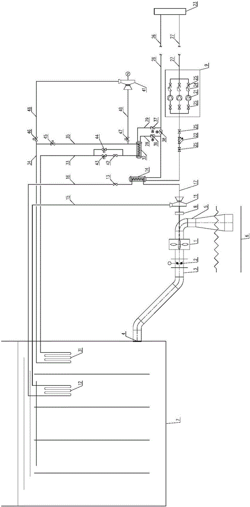
[0034] refer to figure 1 Shown: a thermal power station tail water recovery device, characterized in that: a water energy recovery culvert 3 is provided at the outlet of the pressure forebay 7, and a water energy recovery culvert 3 and a tail water culvert 5 are provided between the described water energy recovery culvert 3 and the tail water culvert 5 The water turbine 1 is equipped with a filter screen 4 at the water outlet of the pressure forebay 7, and communicates with the water energy recovery culvert 3, and a butterfly valve 2 is arranged on the water energy recovery culvert 3. The tail of the tail water culvert pipe 5 is inserted into the water source 6, a spee...


PUM


Abstract

The invention discloses a recycling device for thermal power station tail water and a utilizing method. The recycling device for the thermal power station tail water is characterized in that a refrigerating compressor (11) is directly driven through a water turbine (1); a first condenser (12) and a second condenser (13) in a refrigerating cycle system are arranged in a pressure forebay (7) and are cooled by water; a natural refrigerating manner is adopted for a second evaporator (32) in winter, and a mechanical refrigerating manner is adopted for the second evaporator (32) in summer and transition seasons; the first refrigerating compressor (11), a second air pipe (17), a first evaporator (14), a first expansion valve (13), a first liquid pipe (16), the first condenser (12) and a first air pipe (15) are sequentially connected in series; and the first evaporator (14), a chilled water returning pipe (26), an auxiliary machine equipment cooling water system (23), a chilled water supplying pipe (27), a pump set (9) and a water filter (22) are sequentially connected in series. Compared with the prior art, the recycling device has the beneficial effects of cyclic water use, cascading water use and multiple purposes of one kind of water are achieved.

Description

technical field [0001] The invention relates to a once-through cooling water system, and more specifically relates to a tail water recovery device and a utilization method of a thermal power station. Background technique [0002] The design location of the thermal power station site is relatively high, above the 100-year control flood level. [0003] The thermal power station using the once-through cooling water system is located in an area rich in water resources in the south, and is close to the water source. The temperature and drainage water surface of the outlet is equal to the dry water level of the water source (river, river, reservoir, etc.) throughout the year P=97% catch. Thermal power plants have unique advantages in recovering circulating water drainage (tail water) heads. [0004] In order to improve economic efficiency, domestic thermal power plants using once-through cooling water systems generally achieve energy saving by setting up hydro-generators in the ...

Claims


Application Information

Patent Timeline
Patent Type & Authority Applications(China)
IPC IPC(8): F25B1/00F25B41/00F25B41/04F25B41/06F25B41/20F25B41/325F25B41/40
CPCF03B13/00F25B1/00F25B41/40F25B41/31F25B41/20
Inventor 李文胜王志军力顺
Owner CENT SOUTHERN CHINA ELECTRIC POWER DESIGN INST CHINA POWER ENG CONSULTING GROUP CORP
Why Eureka
Try Eureka