
Distributed photovoltaic energy storage peak regulation system based on power prediction

A distributed photovoltaic and power forecasting technology, applied in photovoltaic power generation, energy storage, renewable energy integration, etc., can solve the problems of insufficient proportion of distributed photovoltaic self-generation and self-use, and insufficient proportion of distributed photovoltaic power generation and self-use

Active Publication Date: 2016-10-26
姜宪明 +1
View PDF5 Cites 15 Cited by
  • Summary
  • Abstract
  • Description
  • Claims
  • Application Information

AI Technical Summary

Problems solved by technology

[0005] Aiming at the problem of insufficient proportion of self-consumption of distributed photovoltaic power generation, the present invention proposes a distributed photovoltaic energy storage peak-shaving system based on power prediction. While the proportion of self-use is insufficient, it can further realize the use of peak and valley electricity prices to cut peaks and fill valleys, and as a backup power supply to improve the reliability of the power supply system

Method used


Image

  • Distributed photovoltaic energy storage peak regulation system based on power prediction
  • Distributed photovoltaic energy storage peak regulation system based on power prediction
  • Distributed photovoltaic energy storage peak regulation system based on power prediction

Examples


Embodiment 1

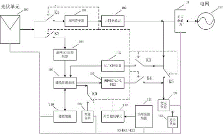
[0021] The distributed photovoltaic energy storage peak-shaving system based on power prediction includes: photovoltaic unit (100), grid-connected inverter (101), grid-connected electric energy meter (102), gateway electric energy meter (103), grid (137), Grid DC / DC controller (104), AC / DC controller (105), energy storage management system (106), off-grid DC / AC controller (107), DC load (108), AC load (109), Energy storage device (110), power prediction device (111), switch control unit (112), communication unit (113), controlled switches K0, K1, K2, K3, K4, K5, etc.

[0022] The connection method of each part is as figure 1 As shown, the specific connection method is as follows: the photovoltaic unit (100) is connected to the controlled switches K1 and K2, the input of the grid-connected inverter (101) is connected to the controlled switch K1, and the output of the grid-connected inverter (101) is connected to The input of the grid-connected electric energy meter (102) is connec...

Embodiment 2

[0025] In the distributed photovoltaic energy storage peak-shaving system based on power prediction, distributed photovoltaic is mainly connected to the grid, and off-grid is the auxiliary. Only when the mains power is out of power, in order to maximize the use of distributed photovoltaic power, the distributed photovoltaic can work in Off-grid status, K1 closed indicates that the grid is normal and the distributed photovoltaic is working or planned to work in the grid-connected state, K2 closed indicates that the grid has been powered off and the distributed photovoltaic is working or planned to work in the off-grid state, and K3 and K5 are closed even when K2 is closed Cannot supply power to the downstream equipment. It is defined that K1 and K2 cannot be closed at any time. When K2 is closed, either K3 or K5 cannot be closed. K4 and K5 cannot be closed at any time. K3 and K4 are not at the same time. In the closed state, after the 64 switch states formed by K0~K5 exclude the ...

Embodiment 3

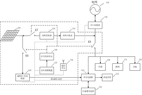
[0032] The distributed photovoltaic energy storage peak shaving system based on power prediction provides a method suitable for transforming power supply systems with energy storage devices, such as communication base station power supply systems, power supply systems with backup UPS, etc., without changing the original system power supply structure Under the premise, through appropriate addition of photovoltaic arrays (122), grid-connected inverters (123), grid-connected energy meters (124), off-grid DC / DC controllers (125), communication units (126), and power prediction devices (127), the switch control unit (128), and the controlled switches K6, K7, K8, etc. used to realize electric energy dispatch, to realize a distributed photovoltaic energy storage peak shaving system that meets the basic needs of users. image 3 In the system schematic diagram shown, the outside of the dashed box is the configuration diagram of the power supply system of the standard communication base st...


PUM


Abstract

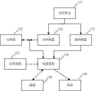
The invention relates to a distributed photovoltaic energy storage peak regulation system based on power prediction, which comprises a photovoltaic unit, a grid-connected device, a power grid end, an off-grid device, power prediction, electric power dispatching, an energy storage device, loads and the like. The whole system is composed of the photovoltaic unit, a grid-connected inverter, a grid-connected electric energy meter, a gateway electric energy meter, a power grid, an off-grid DC / DC controller, an AC / DC controller, an energy storage management system, an off-grid DC / AC controller, a DC load, an AC load, an energy storage device, a power prediction device, a switch control unit, a communication unit, controlled switches K0, K1, K2, K3, K4 and K5 and the like. The output of the power prediction controls the state of the controlled switch via the switch control unit, and thus, the distributed photovoltaic energy storage peak regulation system based on power prediction can dispatch the residual capacity of the energy storage device in advance, and the following purposes can be realized: when future photovoltaic output is larger than the load, the redundant photovoltaic electric energy is stored by the energy storage device, the distributed photovoltaic self-generation self-use ratio maximization is realized, and the distributed photovoltaic income level is improved; in the case of future mains supply failure, the part with insufficient load is provided by the energy storage device and the photovoltaic off-grid power supply device, and the reliability of the power supply system is improved; and functions of peak load shifting are provided for areas with significant step tariff, the comprehensive utilization rate of the system is improved, and the income level is improved.

Description

Technical field [0001] The invention relates to a distributed photovoltaic energy storage peak regulation system based on power prediction, and belongs to the application field of new energy and distributed photovoltaic energy storage peak regulation. Background technique [0002] Energy and environmental issues are an important factor restricting economic and social development. The use of traditional energy has great environmental costs. Photovoltaic power generation belongs to the field of new energy power generation, and its environmentally friendly features are a breakthrough in solving energy and environmental problems. In recent years, China has built a large number of large-scale ground-based photovoltaic power stations, which have left some negative effects while promoting the development of the photovoltaic industry. Due to land use restrictions, large-scale photovoltaic power stations are mostly built in sparsely populated, deserted, and deserted areas in the northwest....

Claims


Application Information

Patent Timeline
IPC IPC(8): H02J3/32H02J3/46H02J9/06
CPCH02J3/32H02J3/46H02J9/061H02J9/068Y02B10/70Y02E10/56Y02E70/30
Inventor 姜宪明高爽
Owner 姜宪明
Learn More