Wind turbine drive train

A technology for wind turbines and driving mechanisms, which is applied in the directions of wind turbines, wind turbine control, wind turbine combination, etc., can solve problems such as discrete supports, and achieve the effects of reducing the number, reducing the cost of components, and reducing subsequent loads.

Inactive Publication Date: 2016-10-26
纳巴风力公司
View PDF7 Cites 1 Cited by
  • Summary
  • Abstract
  • Description
  • Claims
  • Application Information

AI Technical Summary

Problems solved by technology

However, there are many problems with this construction: the huge main shaft size relative to the two separate rolling supports present in the narrow ring supporting it, the considerable weight of the multiple generators (which feed at least 9 generators) and the resulting frame Complexity to prevent excessive bending of the double supporting main shaft and accommodate the central wheel and all subsequent generators
However, as a new invention, the patent document US2009250939A1 proposes a continuous rolling raceway, but with discrete supports

Method used


Image

  • Wind turbine drive train
  • Wind turbine drive train
  • Wind turbine drive train

Examples


Embodiment Construction

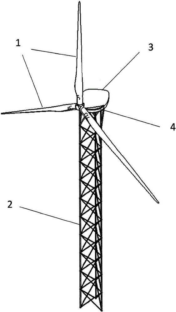
[0029] figure 1 The wind turbine shown is a horizontal axis wind turbine with three blades (1) facing downwind and a lattice tower (2) whose three legs are equal to each other along its entire length separated by distance. A connecting piece (4) is arranged between the nacelle (3) and the tower (2), on which connecting piece (4) the drive mechanism of the object of the invention (not shown in the figure) is arranged.

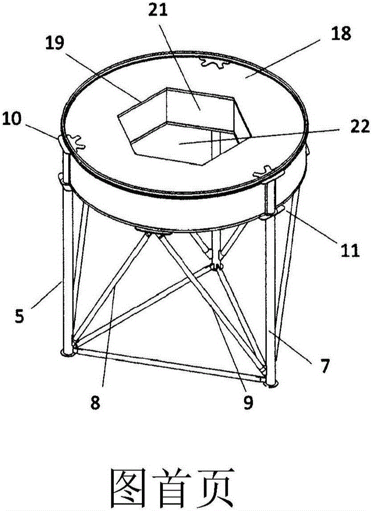
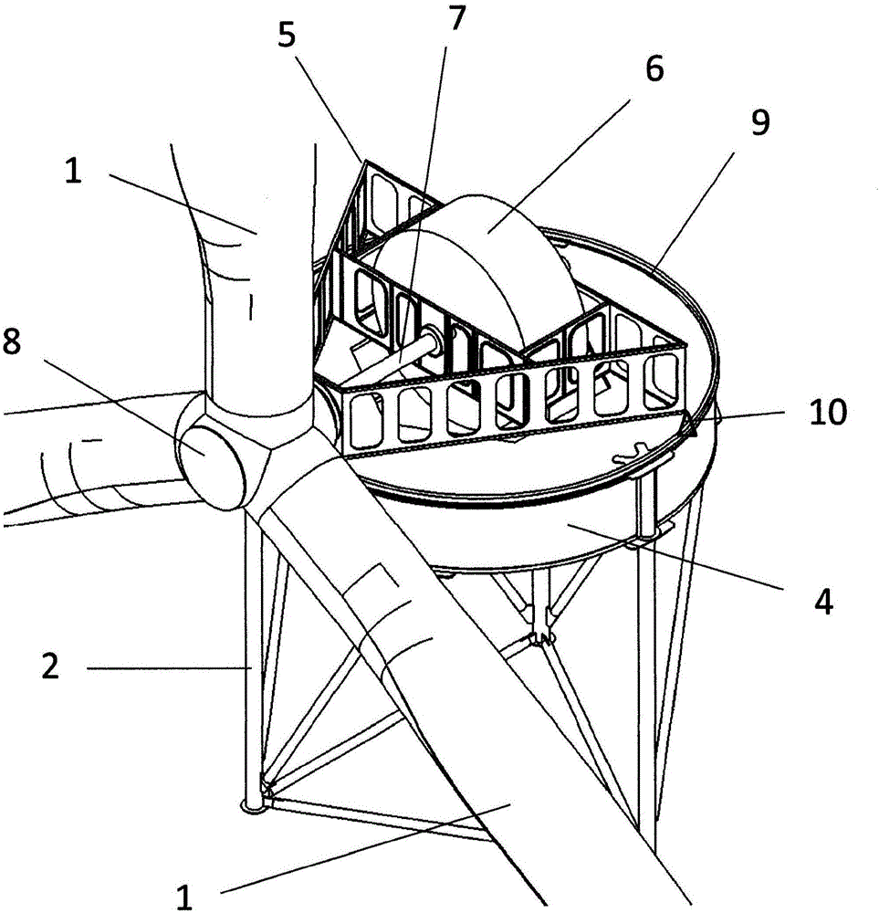
[0030] like figure 2 and image 3 As shown, the lattice tower (2) supports the connector (4), the triangular main frame (5) houses the generator (6) and the main shaft (7) inside and supports the rotor (8) at one end thereof, and the triangular The main frame (5) is arranged on the connecting piece (4). The rolling ring or raceway (9) is part of the rotation system (yaw) and is arranged on top of the link (4). Said rotation system consists of the mentioned ring (9) and three supports (10) each arranged at each vertex of the triangle forming the main frame ...


PUM


Abstract

Wind turbine drive train with a nacelle (3) as much compact as possible in a tower (2) with a big diameter which allows to embed the generator (6) inside and reduce the loads in the supports (10) of the yaw system and in the tower (2). The mainframe (5) of the nacelle (3) has a triangular shape based on structural frames or ribs, taking profit of the big reaction arm with the most compact solution. The generator (6) is integrated in this mainframe (5) and partially crosses the connection piece (4) of the tower (2). The yaw system is made by individual supports in a continuous raceway and the traction elements provokes the rotation of the nacelle (3) around the tower (2) without the need of the usual geared pinion - zip systems, using pneumatic wheels (20) which roll by the raceway made by the rotation ring (9) with inverted T shape with one or two circular sections on the top of its profile.

Description

technical field [0001] The invention is included in the field of wind turbines and, more specifically, in the field of drive mechanisms in which a direct-coupled generator inside a nacelle is attached by its corresponding transmission to a wind rotor arranged outside the nacelle. Background technique [0002] Currently known are drives without step-up transmissions, ie with a generator directly coupled to the rotor. M Torres and Jeumount designs added to ENERCON E-30, E-40 and other machines. Currently, Siemens, Areva, Alstom, Vestas, Ming Yang, Goldwin or IMPSA have developed this type of structure. It can thus be concluded that the configuration of a generator directly coupled to the rotor is known from the prior art, which configuration also includes a generator frequency converter for decoupling said generator from the grid. [0003] The function of the main frame of the nacelle is, in any case, to support the drive mechanism and to transmit the load from the rotor to...

Claims


Application Information

Patent Timeline
Patent Type & Authority Applications(China)
IPC IPC(8): F03D80/00F03D15/00F03D80/80F03D9/25F16C19/54F03D1/06
CPCF03D7/0204F03D15/00F03D15/20F03D80/00F03D80/70F03D80/80F03D80/88F16C19/507F16C2300/14F16C2360/31Y02E10/72
Inventor E·桑泽·巴斯库尔H·R·萨维·科斯塔
Owner 纳巴风力公司
Why Eureka
Try Eureka