Solvent oil gas recycling apparatus

A recovery device, oil and gas technology, applied in combination devices, grease/oily substance/float removal devices, immiscible liquid separation, etc. problem, to achieve the effect of convenient disassembly and washing function, long service life, and improved processing and recycling efficiency

Active Publication Date: 2016-11-02
ZHEJIANG HUAQIANG ENVIRONMENTAL TECH
View PDF6 Cites 5 Cited by
  • Summary
  • Abstract
  • Description
  • Claims
  • Application Information

AI Technical Summary

Problems solved by technology

[0004] At present, most solvent oil gas recovery devices generally have the following problems: 1. The gas treatment effect is not ideal, and the solvent recovery effect is poor; 2. After long-term use, the processing capacity of the system decreases and the treatment effect weakens; 3. It is difficult to maintain and the service life is short

Method used


Image

  • Solvent oil gas recycling apparatus
  • Solvent oil gas recycling apparatus
  • Solvent oil gas recycling apparatus

Examples


Embodiment 1

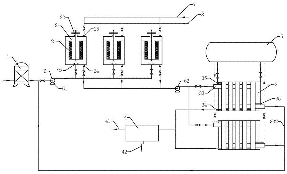
[0040] according to Figure 1 to Figure 8 As shown, a solvent oil gas recovery device includes: a coarse filter 1, an adsorption tank 2, two parallel condensation filters 3, an oil-water separator 4, a refrigerator 5, a fan 6, a steam pipeline 7 and a hot gas pipeline 8, and the steam The temperature of the steam in the pipeline 7 is 100-200°C, the temperature of the hot gas in the hot-gas pipeline 8 is 60-100°C, and the temperature in the condensation filter 3 is controlled at -10-5°C;

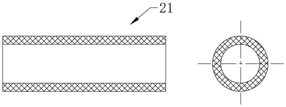
[0041] The number of adsorption tanks 2 is 3, which are set in the way of one desorption and two suctions. Each adsorption tank 2 includes a fiber activated carbon layer 21, a purified gas outlet 22, a waste gas inlet 23 connected with the coarse filter 1, and a desorption gas outlet 24. And the desorption gas inlet 25, the desorption gas outlet 24 is communicated with the condensation filter 3, the desorption gas inlet 25 is communicated with the steam pipeline 7 and the hot gas pipeline 8, ...

Embodiment 2

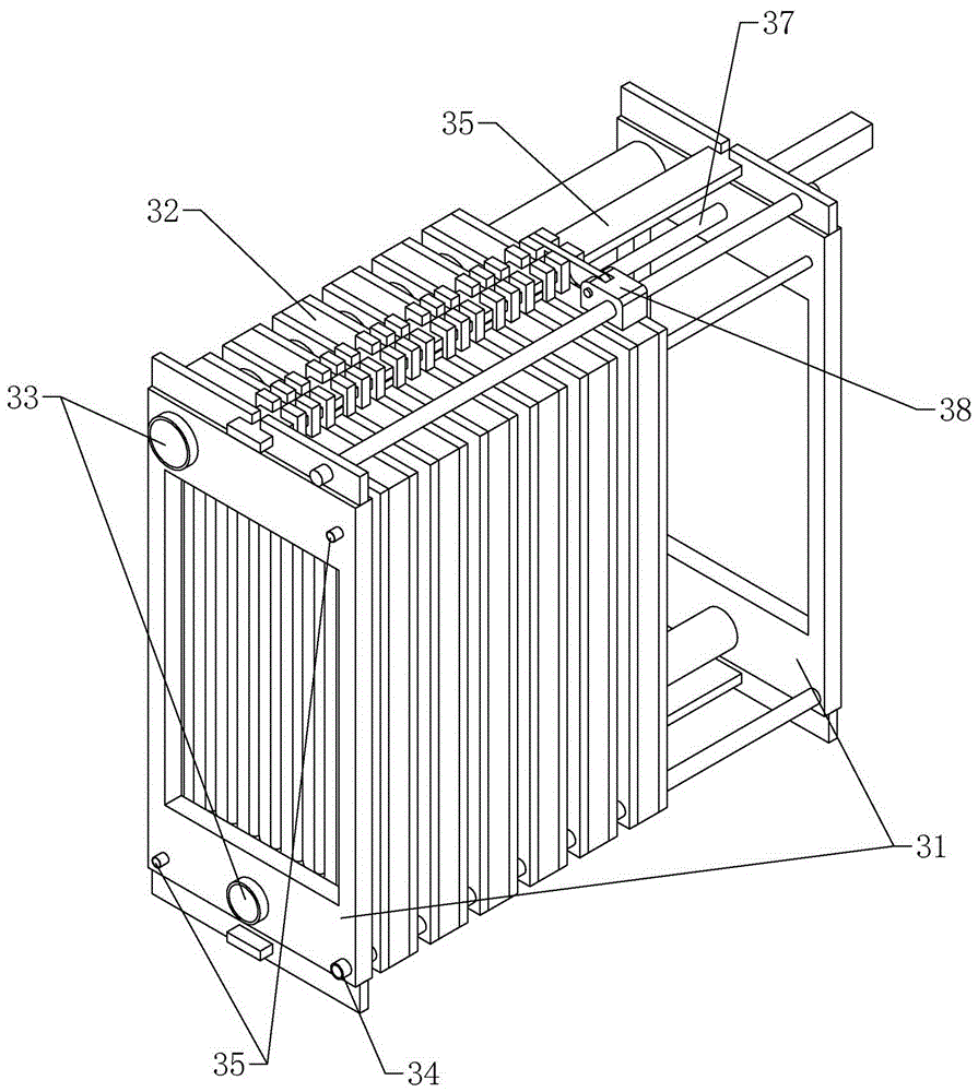
[0055] The difference from the above-mentioned embodiment 1 is that, according to image 3 , Figure 4 As shown, a separation mechanism 38 is also provided on the shelf plate 31, the separation mechanism 38 includes a slide bar 381 and a separator 382, ​​the slide bar 381 is a screw rod, and the separator 382 includes a slide table 3821 and a hinged joint arranged on the slide bar 381. The driving rod 3822 on the slide table 3821 is controlled by the motor provided on the slide table 3821, and can rotate up and down, thereby selecting the slide block 326 to move.

[0056] In the device cleaning process of this embodiment, the difference from Embodiment 1 is that when the device is cleaned, after the pressure rod 371 is loosened, the first filter plate 32a, the second filter plate 32b and the sealing backing plate of the condensation filter unit 32 32c are separated one by one under the drive of separation mechanism 38, which saves manpower.

Embodiment 3

[0058] The difference from the above-mentioned embodiment 2 is that, according to Figure 7 As shown, the slide bar 381 is also provided with a backwash spray head 39 that can slide along the slide bar 381. The backwash spray head 39 includes a mobile platform 391, a spray bar 392 hinged on the mobile platform 391 and a spray bar connected to the mobile platform 391. Water inlet pipe 393. After the first filter plate 32a, the second filter plate 32b and the sealing backing plate 32c of the condensation filter unit 32 are separated under the action of the separation mechanism 38, they are cleaned by the backwash nozzle 39, which improves the automation of the equipment.


PUM


Abstract

The invention relates to a recycling apparatus and particularly relates to a solvent oil gas recycling apparatus. The apparatus includes a rough filter, a plurality of adsorption tanks, at least two condensing filters which are connected in parallel, an oil-water separator, a refrigerator, an air blower, a vapor pipeline, and a hot air pipeline. The adsorption tank includes a fiber activated carbon layer, a purified gas outlet, a waste gas inlet which is connected to the rough filter, desorption gas outlets, and desorption gas inlets. The desorption gas outlets are connected to the condensing filters. The desorption gas inlets are connected to the vapor pipeline and the hot air pipeline. The condensing filters are self-cleaning condensing filters, each of which includes a frame board, a plurality of condensing filter unit, a gas pipe, a recycling pipe, a condensing pipe, a slide rail, and a pressing mechanism. The end of the gas pipe is connected to a gas backflow pipe which is then communicated with the adsorption tanks. The oil-water separator is communicated with the recycling pipe and is provided with a recycled water outlet and a solvent recycling outlet. The refrigerator is communicated with the condensing pipe.

Description

technical field [0001] The invention relates to a recovery device, in particular to a solvent oil gas recovery device. Background technique [0002] A large amount of organic waste gas will be generated in the production and use of printing and dyeing, medicine, chemical fiber, printing, coating, gluing, plastics, photosensitive materials, synthetic rubber, and many petrochemical products and coking products. By recycling the resources in the waste gas discharged from industrial production, the recovered solvent can be reused, and the recovered solvent can be used for equipment investment, which is greatly welcomed by the government and users. Therefore, this technology is beneficial to the country and the people. It not only effectively controls the emission of exhaust gas, achieves the purpose of clean and environmentally friendly production, but also enables the recycling of precious resources, and can bring considerable economic benefits to users. [0003] In recent yea...

Claims


Application Information

Patent Timeline
Patent Type & Authority Applications(China)
IPC IPC(8): B01D50/00B01D53/00C02F1/40B01D46/00B01D17/02
CPCB01D17/02B01D46/0012B01D50/00B01D53/002C02F1/40
Inventor 唐建强
Owner ZHEJIANG HUAQIANG ENVIRONMENTAL TECH
Why Eureka
Try Eureka