Device and method for monitoring hydraulic turnover angle of molten steel ladle
A technology for hydraulic flipping and angle monitoring, applied in measuring devices, instruments, etc., can solve the problem of inability to monitor the flipping angle of the ladle in real time, and achieve the effect of meeting the requirements of intelligent control, ensuring stability, and realizing automatic control.
- Summary
- Abstract
- Description
- Claims
- Application Information
AI Technical Summary
Problems solved by technology
Method used
Image
Examples
Embodiment 1
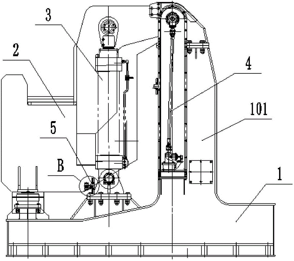
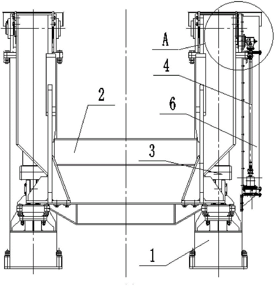
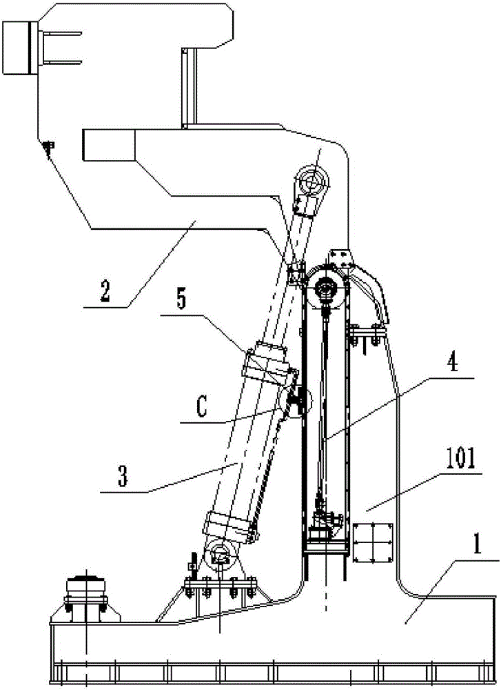
[0044] like Figure 1 to Figure 5 As shown, a ladle hydraulic tilting angle monitoring device in this embodiment includes a base 1 , a movable support 2 , an oil cylinder 3 and a rotation angle measuring mechanism 4 . Wherein, the base 1 has a column 101, the upper end of the movable support 2 and the column 101 is hingedly connected by a pin; one end of the oil cylinder 3 is hingedly connected with the base 1, and the other end is hingedly connected with the movable support 2.
[0045] When using the above-mentioned device to complete the ladle overturning process, the overturning angle of the ladle is a very important index. Through it, information such as the position of the ladle, the dumping status of the molten steel, and the stable operation of the equipment can be known. It is important for the stability of the equipment operation, Reliability and security are paramount. However, the measurement of the tipping angle of the ladle is very difficult, and several problems...
Embodiment 2
[0055] A ladle hydraulic flip angle monitoring device of this embodiment is basically the same as Embodiment 1, the difference is that: the device is provided with a position sensing device 5; figure 1 , image 3 , Image 6 and Figure 7 , the position sensing device 5 is provided with two, one is used to detect whether the movable support 2 is in the initial state position, and the other is used to detect whether the movable support 2 is in the position of the maximum tipping state, so that the operating state of the movable support 2 can be understood , it is convenient for the control system to control the action of the oil cylinder 3, and the time for pouring the molten steel from the ladle can be controlled through the control system to meet the requirements of intelligent control. Specifically, the position sensing device 5 includes a sensing trigger component 510 and a sensing receiving component 520. The sensing triggering component 510 includes a sensing touch panel...
Embodiment 3
[0058] A ladle hydraulic flip angle monitoring device of this embodiment is basically the same as Embodiment 2, except that the induction receiving component 520 includes a protection box 522, a rectangular tube 523 and a splint 524 in addition to the induction switch 521 , combined with figure 1 , image 3 , Image 6 , Figure 7 and Figure 8 , the rectangular tube 523 is set on the base 1 or the column 101 of the base 1, the protective box 522 is installed on the rectangular tube 523, the induction switch 521 is arranged in the protection box 522, and the induction switch 521 is protected to avoid damage; the rectangular tube 523 is provided with an adjustment slot along the length direction, and the protection box 522 is connected with the splint 524 arranged in the rectangular tube 523 through the adjustment slot of the rectangular tube 523 through bolts. In this structure, the installation position of the protection box 522 on the rectangular tube 523 Adjustable, it i...
PUM
 Abstract
Description
Claims
Application Information
 - R&D
- Intellectual Property
- Life Sciences
- Materials
- Tech Scout
- Unparalleled Data Quality
- Higher Quality Content
- 60% Fewer Hallucinations
Browse by: Latest US Patents, China's latest patents, Technical Efficacy Thesaurus, Application Domain, Technology Topic, Popular Technical Reports.
© 2025 PatSnap. All rights reserved.Legal|Privacy policy|Modern Slavery Act Transparency Statement|Sitemap|About US| Contact US: help@patsnap.com


