Hydraulic suspension type cotton top-cutting machine

A technology of hydraulic suspension and topping machine, which is applied to agricultural machinery and implements, cutting tools, cutting equipment, etc., can solve the problems of inability to realize the immediate profiling of a single cotton plant, inaccurate adjustment of height, hitting peach, etc. The effect of cotton planting cost, reduction of equipment purchase cost, accurate identification and tracking

Pending Publication Date: 2016-11-09
祖元丁
View PDF0 Cites 1 Cited by
  • Summary
  • Abstract
  • Description
  • Claims
  • Application Information

AI Technical Summary

Problems solved by technology

3MDY-12 front suspension hydraulic drive, hydraulic lifting cotton topping machine, topping height 500-900mm, 3MDZY-12 rear suspension hydraulic drive, hydraulic lifting cotton topping machine, topping height 500-900m], but existing The topping machines are powered by ordinary tractors with a ground clearance of 400-450mm and poor passability; the manual operation of the lifting control device makes the height adjustment inaccurate and untimely; the existing machines cannot realize the random profiling of individual cotton plants, During the operation of the top machine, the phenomenon of missing beating, beating bells, beating peaches, and damaging cotton leaves occurred
[0005] To sum up, the above models have their own innovation points, and correspondingly solve some technical difficulties in the cotton mechanical topping operation, but none of them can well adapt to the agronomic technical requirements of cotton mechanical topping, and there is no one yet. The cotton topping machine put into field topping operation

Method used


Image

  • Hydraulic suspension type cotton top-cutting machine
  • Hydraulic suspension type cotton top-cutting machine
  • Hydraulic suspension type cotton top-cutting machine

Examples


Embodiment Construction

[0034] The structural principles and implementations of the present invention will be described in detail below in conjunction with the accompanying drawings.

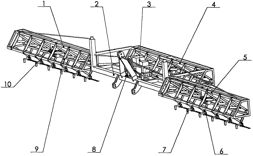
[0035] figure 1 Cotton topping machines in China are usually matched with tractors with rear suspension and power output shafts with high ground clearance (above 700mm). The number of rows of topping machines can be configured according to the power of the tractor. Multi-row and wide-width topping machines use The split truss structure can be folded on both sides. The overall height adjustment of the hydraulic suspension cotton topping machine is controlled by the rear suspension joystick of the tractor manually operated by the driver, and the height of the overall truss should be controlled at the height where the four-bar tracking mechanism 9 is in the middle of the full stroke and equal to the average plant height.

[0036] figure 1 The inclined beam planes of the split trusses 1, 4, and 5 of the cotton topping ma...


PUM


Abstract

The invention provides a hydraulic suspension type cotton top-cutting machine. The hydraulic suspension type cotton top-cutting machine comprises a main rack connected with a tractor hydraulic suspension mechanism, a hydraulic station and a power generation station which are mounted on the main rack and are driven by a tractor power output shaft, a middle truss connected to the rear end of the main rack, splitting trusses connected to the left and right ends of the main rack, at least one group of hydraulic four-rod tracking mechanism distributed on the middle truss and the left and right splitting trusses, at least one group of top-cutting executing device connected to the lower ends of movable vertical rods of the hydraulic four-rod tracking mechanisms, at least one group of plant top identification device connected to the front sides of the top-cutting executing devices, and a plant top identification and tracking automatic control system for connecting the plant top identification devices with the hydraulic four-rod tracking mechanisms; the top-cutting executing devices adopt direct-current motor driven reciprocating cutters. The hydraulic suspension type cotton top-cutting machine is matched with a high-clearance tractor and has independent hydraulic and electric systems and adjustable row spacing; copying top-cutting work has no front-back interference problems under single-ridge dense planting conditions.

Description

technical field [0001] The invention relates to a cotton field management machine, in particular to a hydraulic suspension cotton topping machine. Background technique [0002] For a long time, the domestic cotton topping work has been mainly done manually, but manual topping has a large demand for labor force, low efficiency, and harsh working environment. Reduced cotton yield. In the whole process of mechanization of cotton production, mechanization has been basically realized in all links from arable land to fertilization, weeding, sowing, seedling setting, chemical control, irrigation, and cotton harvesting, but the mechanization of cotton topping is lagging behind. Manual topping has been unable to meet the needs of full-scale mechanization of large-scale cotton production, which has seriously restricted the growth of cotton production. [0003] There are some early research results on cotton topping machinery in foreign countries. Both the suspended type and the self...

Claims


Application Information

Patent Timeline
IPC IPC(8): A01G3/08A01G7/06
CPCA01G3/085A01G7/06
Inventor 祖元丁李汶罡刘兆国
Owner 祖元丁
Why Eureka
Try Eureka