Dry-wet combined desulfurization dedusting device resistant dewing of fan

A technology for desulfurization and dust removal and dust removal devices, which is applied in the direction of combined devices, gas treatment, membrane technology, etc., can solve the problems of fan impeller dust accumulation, high flue gas temperature, and low flue gas temperature drop, so as to prevent condensation and improve the treatment process Simple, mission-life-extending effects

Inactive Publication Date: 2016-11-09
天津寰泰科技有限公司
View PDF1 Cites 0 Cited by
  • Summary
  • Abstract
  • Description
  • Claims
  • Application Information

AI Technical Summary

Problems solved by technology

[0002] At present, the desulfurization and dust removal devices for flue gas produced by boilers, kilns, etc. are divided into two types: dry type and wet type. The existing wet type desulfurization and dust removal devices have high dust removal efficiency, but when processing flue gas, the humidity of the flue gas increases and the temperature drop is relatively large. When the treated flue gas is discharged from the outlet at the top of the tower, the humidity is very high, and it is basically saturated under normal circumstances, while the temperature is relatively low, generally around 60°C. This kind of flue gas is cooled again through the flue, and knots appear on the fan. The phenomenon of dew will cause dust accumulation on the fan impeller and cause corrosion, which will cause the fan to vibrate, which will obviously affect the normal operation of the boiler, and the chimney exhaust smoke will not rise well, which is not conducive to the emission of pollutants
[0003] The dust removal efficiency of the dry dust removal device is low, and it does not have the desulfurization function. Simply using the dry dust removal device to treat the flue gas cannot meet the current national emission standards. Flue gas temperature is high, humidity changes little

Method used


Image

  • Dry-wet combined desulfurization dedusting device resistant dewing of fan
  • Dry-wet combined desulfurization dedusting device resistant dewing of fan
  • Dry-wet combined desulfurization dedusting device resistant dewing of fan

Examples


Embodiment Construction

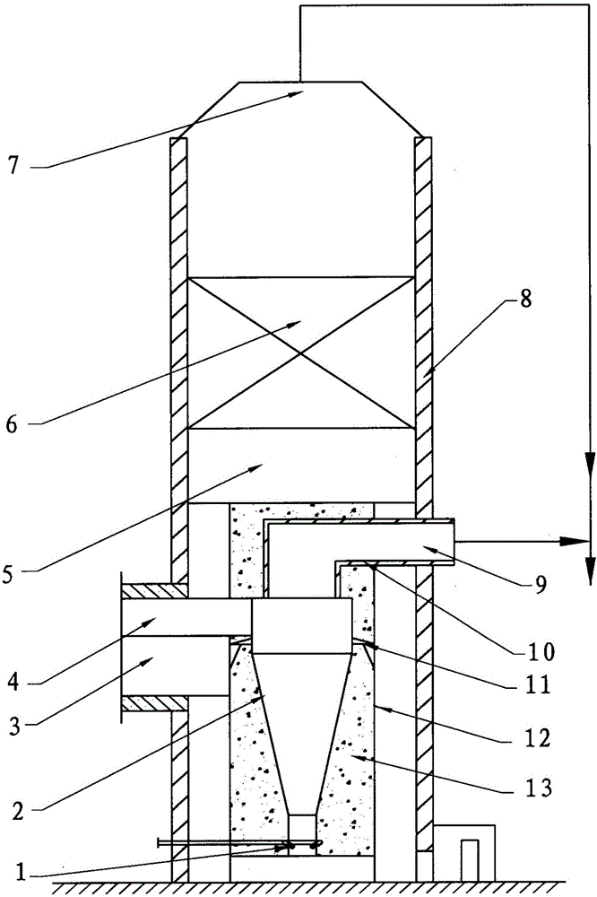
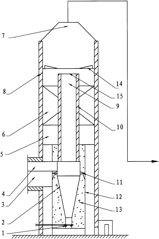
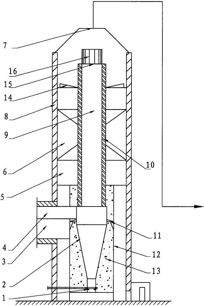
[0017] Such as figure 1 , The present invention consists of a wet desulfurization and dust removal device and a dry dust removal device. The dry dust removal device is composed of an inlet flue 4, a dry dust collector 2 and an outlet flue 9. The dry dust collector 2 can be a single cyclone separation dust collector, Multi-tube cyclone separation dust collector, bag filter, electric dust collector and other dry dust collectors.

[0018] The wet desulfurization and dust removal device consists of an inlet flue 3, a wet desulfurization and dust removal tower 5, and an outlet flue 7. The wet desulfurization and dust removal tower 5 can be a spray tower, a packed tower, a swirling plate tower, a turbulent plate tower, a sieve plate tower, and turbulent flow. Plate towers such as towers, turbulence towers, bubble towers, and other wet desulfurization and dust removal towers.

[0019] A sealed inner cylinder 12 is arranged inside the wet desulfurization and dust removal tower 5, the dry d...


PUM


Abstract

The invention discloses a dry-wet combined desulfurization dedusting device resistant dewing of a fan. The dry-wet combined desulfurization dedusting device is composed of a wet desulfurization dedusting device and a dry dedusting device, the dry dedusting device is composed of an inlet flue, a dry deduster and an outlet flue, the wet desulfurization dedusting device is composed of an inlet flue, a wet desulfurization dedusting tower and an outlet flue, a sealed inner barrel is arranged inside the wet desulfurization dedusting tower, the dry deduster is arranged in the sealed inner barrel, and the outlet flue of the dry dedusting device is communicated with the outlet flue of the wet desulfurization dedusting device. The dry-wet combined desulfurization dedusting device combines the wet and dry dedusting devices, respective advantages can be brought into play, treated smoke can reach national emission standards, temperature is higher than dewing point temperature, dewing of the fan is avoided, and corrosion, ash accumulation and vibration of the fan caused by the smoke are reduced.

Description

Technical field [0001] The invention relates to a desulfurization and dust removal device, in particular to a dry and wet combination type desulfurization and dust removal device. Background technique [0002] At present, the flue gas desulfurization and dust removal devices produced by boilers, furnaces, etc. are divided into dry and wet types. The existing wet desulfurization and dust removal devices have high dust removal efficiency, but when the flue gas is processed, the humidity of the flue gas increases and the temperature drop is large. The treated flue gas has a high humidity when it is discharged at the top outlet of the tower. Under normal circumstances, it is basically saturated, but the temperature is relatively low, generally around 60 ℃. This flue gas is cooled down again through the flue, and the fan appears The dew phenomenon causes dust accumulation on the fan impeller and corrosion, which causes the fan to vibrate, which obviously affects the normal operation o...

Claims


Application Information

Patent Timeline
Patent Type & Authority Applications(China)
IPC IPC(8): B01D50/00B01D53/78B01D53/48B01D53/18
CPCB01D50/00B01D53/1456B01D53/18B01D53/48B01D53/78B01D2258/0283B01D50/40B01D50/60
Inventor 徐桂泉
Owner 天津寰泰科技有限公司
Why Eureka
Try Eureka