
Flotation column separation equipment and separation method

A flotation column and separation technology, applied in flotation, solid separation and other directions, can solve the problems that the flotation column is difficult to achieve the ideal separation effect, the tailings grade is difficult to meet the requirements, and the countercurrent mineralization is not sufficient. The effect of ensuring the recovery rate of concentrate, improving the efficiency of beneficiation and low production cost

Inactive Publication Date: 2016-11-09
WUHAN INSTITUTE OF TECHNOLOGY
View PDF6 Cites 20 Cited by
  • Summary
  • Abstract
  • Description
  • Claims
  • Application Information

AI Technical Summary

Problems solved by technology

The above-mentioned flotation columns all use cyclones to realize the cyclone mineralization. In the process of use, there are still the following disadvantages: (1) The countercurrent mineralization of the rising air bubbles and the descending pulp in the cyclone flotation columns is not sufficient enough, which is not conducive to the separation (2) The flotation column is easy to be silted and blocked; (3) The ore pulp is easy to form an unstable flow state in the swirling flow, resulting in serious separation entrainment, which is not conducive to separation; (4) Once the scale of the ore pulp processing is expanded, The flotation column is difficult to achieve the ideal separation effect, the tailings grade is difficult to meet the requirements, and the separation index is unstable

Method used


Image

  • Flotation column separation equipment and separation method

Examples


Embodiment 1

[0039] Ore sample from a mining area in Yichang, raw ore P 2 o 5 The grade is 24.64%, and the MgO content is 4.6%. First crush, grind and classify the raw phosphate ore, control the grinding fineness to -200 mesh > 80%, the concentration of the grinding slurry is 30%, and the flotation temperature is about 25°C, and then introduce the slurry into the mineralization tank , the pH value of the pulp is controlled to be 5.6, the fatty acid collector is fully mixed with the pulp at 2.5kg / t, and then the resulting mixture is introduced into the flotation column, and the pulp passes through one or more ore feeders located in the middle and upper part of the flotation column body The tube enters the flotation column, and after flotation, the phosphorous concentrate P 2 o 5 Grade 32.64%, MgO content 0.92%, P 2 o 5 The recovery rate reached 91.8%.

Embodiment 2

[0041] Ore sample from a mining area in Yichang, raw ore P 2 o 5 The grade is 24.84%, and the MgO content is 4.4%. Crushing, grinding and grading the raw phosphate ore, controlling the grinding fineness to -200 mesh > 80%, the concentration of the grinding slurry at 30%, the flotation temperature at about 25°C, adding fatty acid collectors 2.5kg / t, to control the pH value of the slurry to 5.2, the phosphorous concentrate P after flotation 2 o 5 Grade 32.34%, MgO content 0.84%, P 2 o 5 The recovery rate reaches 90.8%.

Embodiment 3

[0043] Ore sample from a mining area in Yichang, raw ore P 2 o 5 The grade is 23.37%, and the MgO content is 4.8%. Crushing, grinding and classifying raw phosphate ore, controlling the grinding fineness to -200 mesh > 80%, the concentration of the grinding slurry at 30%, the flotation temperature at about 25°C, adding fatty acid collector 2.7kg / t, the pH value of the control slurry is 5.8, and the phosphorus concentrate P after flotation 2 o 5 Grade 32.57%, MgO content 0.83%, P 2 o 5 The recovery rate reached 92.6%.


PUM


Abstract

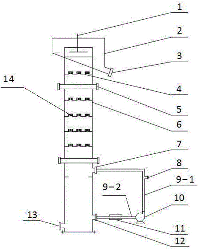
The invention discloses flotation column separation equipment. The flotation column separation equipment comprises a hollow column body. A foam collecting tank, a spraying device and a tailing pipeline are arranged at the top of the column body. A plurality of sieve plates are arranged on the middle-upper portion in the column body. A middling circulating device is arranged on the lower portion of the column body. The middling circulating device comprises a circulating ore pulp outlet, and the circulating ore pulp outlet is sequentially connected with a chemical feeding tank, a middling circulating ore pulp pump, a bubble generator and a circulating ore pulp inlet. A feeding pipe is arranged on the upper portion of the column body. A concentrate pipe is arranged on the lower portion of the column body, and the concentrate pipe is lower than the circulating ore pulp outlet. The invention further provides an ore separation method. According to the flotation column separation equipment and the separation method, the trinity mineralization mode integrating raw ore reverse flow mineralization, middling pipe flow mineralization and middling fluid impact mineralization is adopted, efficient separation of phosphorus ore can be achieved, the production cost is low, and the energy consumption is low.

Description

technical field [0001] The invention relates to the field of ore dressing, in particular to a flotation column sorting device and a sorting method, which are suitable for sorting phosphate rock, other non-metallic ores and metal ores. Background technique [0002] As mineral resources become increasingly poor, fine, and miscellaneous, flotation columns, as a recognized fine-grained mineral separation equipment, have been paid more and more attention by the mineral processing industry. Looking at the research progress of flotation columns in the past few decades, it mainly focuses on reducing the height of the column, the structure of the bubble generator, and the efficient mineralization method. Among them, the research on the specific realization of high-efficiency mineralization has always been a research hotspot in column flotation. [0003] The publication number is 1209360, the publication date is 1999-03-03, and the patent name is the static microbubble flotation colu...

Claims


Application Information

Patent Timeline
Patent Type & Authority Applications(China)
IPC IPC(8): B03D1/14B03D1/02B03D103/06
CPCB03D1/14B03D1/021B03D1/1431B03D2203/06
Inventor 戢峻杨世金吴元欣
Owner WUHAN INSTITUTE OF TECHNOLOGY
Learn More