Rolling mill for three-layer compounded micro-profiled electric contact strip

A micro-shape, electric contact technology, applied in the direction of liquid cleaning method, furnace type, metal rolling, etc., can solve the problems of production difficulty, etc., achieve simple and convenient adjustment, improve annealing effect, and ensure the effect of composite quality

Active Publication Date: 2016-11-09
SUZHOU CHUANGHAO NEW MATERIAL TECH CO LTD
View PDF5 Cites 6 Cited by
  • Summary
  • Abstract
  • Description
  • Claims
  • Application Information

AI Technical Summary

Problems solved by technology

[0003] The above-mentioned rolling mill has the limitation of rolling two-layer or three-layer special-shaped contact strips: only one-sided solder joint materials can be produced. Now, with the multi-functionalization and miniaturization of relays, electronic materials need double-sided s

Method used


Image

  • Rolling mill for three-layer compounded micro-profiled electric contact strip
  • Rolling mill for three-layer compounded micro-profiled electric contact strip
  • Rolling mill for three-layer compounded micro-profiled electric contact strip

Examples


Embodiment 1

[0058] When the above-mentioned rolling mill is actually processing the strip, it is illustrated by taking the preparation of a silver-copper-silver three-layer lateral composite strip with a height of 1.2mm and a width of 2.5mm as an example:

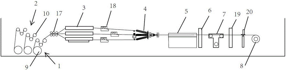
[0059] 1. The pay-off department adopts a pull-type tension sensor to collect and feed back the tension data of the two silver strips (length 60m, width 1mm, height 2mm) and the base copper strip (length 60m, width 5mm, height 2mm) that need to be rolled and compounded. To the PLC main controller to control the pay-off motor;

[0060] 2. The straightening device ensures that the two silver strips and the base copper strip run smoothly and synchronously, ensuring the smooth transition of the strip before entering the compound rolling mill;

[0061] 3. The cleaning tank uses ultrasonic cleaning to clean the two silver strips, uses 5% H2SO4 acid solution to clean the copper strips, and decontaminates the surface of the three metal strips ...

specific Embodiment 2

[0071] The difference between the specific embodiment two and the specific embodiment one is that the preparation height is 1mm, and the silver-kovar alloy (KOVAR alloy)-silver three-layer lateral composite strip with a width of 3 mm adopts 15% H2SO4 acid solution Clean the Kovar alloy, and preheat the Kovar alloy to 800°C. It can also be easily produced by using this rolling mill.

[0072] This rolling mill makes three metal strips rolled and compounded at one time through large plastic deformation. The surface quality of the compounded strips is good and the bonding strength is high; the process of rolling multiple lateral composite strips is continuous and compact, and the adjustment is simple and convenient. The production speed is fast and the product quality is high.


PUM

PropertyMeasurementUnit
Heightaaaaaaaaaa
Widthaaaaaaaaaa

Abstract

The invention discloses a rolling mill for a three-layer compounded micro-profiled electric contact strip. The rolling mill comprises a paying-off part, a paying-off tension part, cleaning troughs, a compounding part, a cooling trough, a universal rolling part, a taking-up tension part and a taking-up part, wherein the paying-off part, the paying-off tension part, the cleaning troughs, the compounding part, the cooling trough, the universal rolling part, the taking-up tension part and the taking-up part are sequentially arranged. The paying-off part comprises a plurality of paying-off frames, the paying-off tension part comprises a plurality of tension control mechanisms, and the compounding part comprises a compounding body and a bidirectional rolling mechanism, wherein a plurality of wire inlet rails are arranged on the side, located at the cleaning troughs, of the compounding body, a wire guiding nozzle is arranged on the other side of the compounding body, and the bidirectional rolling mechanism is arranged on a wire outlet part of the wire guiding nozzle. The universal rolling part comprises a pair of horizontal rollers and a pair of vertical rollers, and the number of the paying-off frames is smaller than that of the tension control mechanisms. The compounded strip rolled by the rolling mill is good in surface quality and high in bonding strength, the strip is compounded laterally in three layers, the process is continuous and compact, and adjustment is easy and convenient.

Description

technical field [0001] The invention relates to the field of rolling mill equipment, in particular to a rolling mill for three-layer composite micro-shaped electrical contact strips. Background technique [0002] At present, the composite micro-shaped electrical contact strips rolled by traditional rolling mills are mostly upper and lower two-layer or three-layer composite strips, which are generally solid-phase rolling composites. According to the rolling temperature, they can be divided into hot-rolled, Cold rolling and warm rolling, the thinnest strip is less than 0.5mm; the three-layer upper and lower composite strips are generally rolled and compounded by two layers of strips, and then rolled and compounded with the third layer of strips, and the three-layer special-shaped contacts The typical shape of the strip is as figure 1 As shown, an electrical contact layer 71 , an intermediate layer 72 and a base layer 73 are sequentially included from top to bottom. Most of t...

Claims


Application Information

Patent Timeline
IPC IPC(8): B21B1/08B21B15/00B21B39/14B21B38/00B21B38/04B08B3/12C23G3/02C21D1/26C21D9/62
CPCB08B3/123B21B1/08B21B15/00B21B38/00B21B38/04B21B39/14B21B2038/004C21D1/26C21D9/62C23G3/021
Inventor 梁贺穆开洪万嵘张弛马云波
Owner SUZHOU CHUANGHAO NEW MATERIAL TECH CO LTD
Why Eureka
Try Eureka