A method and system for nanosecond laser welding of metal sheets

A technology of nanosecond laser welding and thin metal plates, which is applied in laser welding equipment, welding equipment, metal processing equipment, etc., can solve the problems of large thermal deformation due to thermal influence, poor welding strength, and different fusion physical properties, and achieve small pulse width , strong bite force, high peak power effect

Active Publication Date: 2018-10-16
WUHAN HGLASER ENG CO LTD
View PDF11 Cites 0 Cited by
  • Summary
  • Abstract
  • Description
  • Claims
  • Application Information

AI Technical Summary

Problems solved by technology

Because of the difference in laser peak value, the fusion physical characteristics formed are different, so that ms laser welding is used in thin plate dissimilar metals, and thin plate metal welding has problems such as difficult metal fusion and poor welding strength.
At the same time, ms laser welding has a greater thermal impact on materials and thermal deformation

Method used


Image

  • A method and system for nanosecond laser welding of metal sheets
  • A method and system for nanosecond laser welding of metal sheets
  • A method and system for nanosecond laser welding of metal sheets

Examples


Embodiment 1

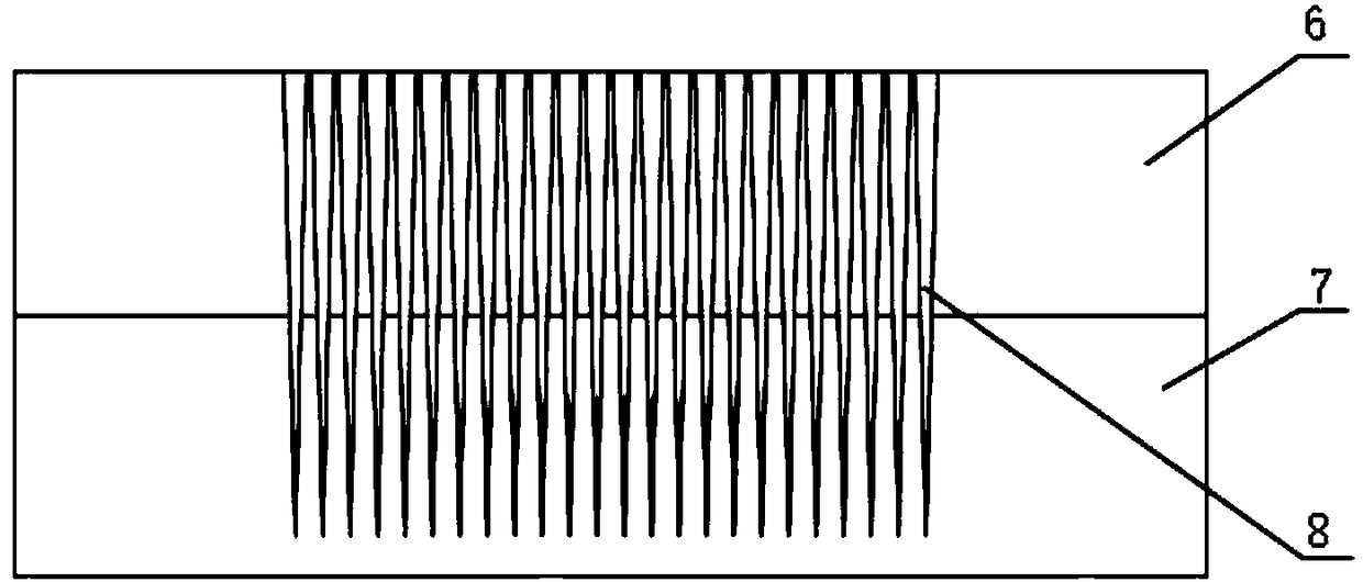
[0023] A method of performing nanosecond laser welding on thin metal plates. The laser beam emitted by the nanosecond laser 1 is emitted to the stacked metal thin plates to be welded to form welding points. Each laser beam penetrates the upper metal thin plate 6 and enters the lower layer. The thin metal plate 7 forms a fine soldering point 8, and the soldering point is formed by a plurality of fine soldering points 8 densely arranged.

[0024] The laser beam is scanned by the galvanometer to scan the deflection device 3 to form a laser beam of a certain size. By controlling the deflection angle of the galvanometer lens, the laser beam can be controlled to emit to the stacked metal sheets to be welded according to a specific trajectory. Several tiny solder joints 8 form nail-shaped occlusal areas at the solder joints. Specifically, each tiny solder joint 8 is filled with gasification or liquefaction of the materials of the upper layer metal sheet 6 and the lower layer metal she...

Embodiment 2

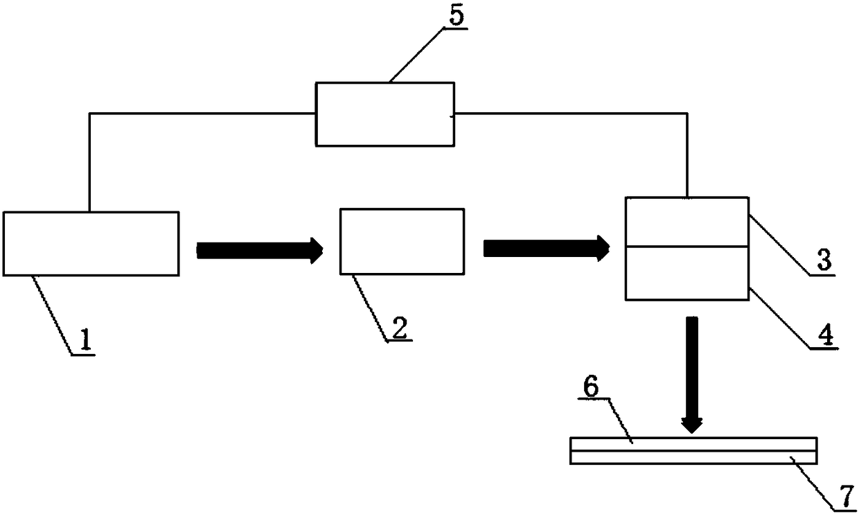
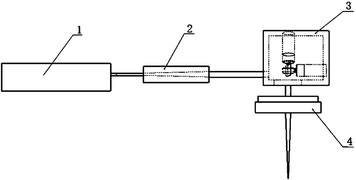
[0032] A system for nanosecond laser welding of thin metal plates, including a nanosecond laser 1, a beam expander 2, a galvanometer scanning deflection device 3, and a beam focusing lens 4 arranged sequentially through a bracket, the laser beam emitted by the nanosecond laser 1 passes through The beam expander 2, the galvanometer scanning deflection device 3, and the beam focusing lens 4 emit to several metal sheets to be welded, and the emission control end of the nanosecond laser 1 and the deflection control end of the galvanometer scanning deflection device 3 are respectively connected to the control The two signal output terminals of device 5.

[0033] The nanosecond laser 1, beam expander 2, galvanometer scanning deflection device 3, and beam focusing lens 4 are respectively arranged on the workbench through a movable bracket, and the beam focusing lens 4 and the galvanometer scanning deflection device 3 are connected by a threaded structure connected.

[0034] Several ...


PUM

PropertyMeasurementUnit
thicknessaaaaaaaaaa
diameteraaaaaaaaaa

Abstract

The invention discloses a method and a system for nanosecond laser welding of metal thin plates. A system for nanosecond laser welding of metal thin plates comprises nanosecond lasers, beam expanders and galvanometers that are sequentially arranged through a bracket for scanning and deflection A device and a beam focusing lens, the laser beam emitted by the nanosecond laser is emitted to several metal sheets to be welded through a beam expander, a galvanometer scanning and deflecting device, and a beam focusing lens. Through the system structure and method of the present invention, the emission time intensity of the nanosecond laser can be controlled by the controller, the deflection angle of the galvanometer scanning deflection device can be controlled by the controller, or the position of the metal sheet to be welded can be adjusted by the sheet holder, The micro-level laser beam generated by the system of the present invention forms a plurality of fine solder joints arranged in a predetermined route on the technical sheet to be welded, which has a stronger occlusal force without excessive heat to the metal. influences.

Description

technical field [0001] The invention belongs to the technical field of laser welding, and in particular relates to a method for welding thin-plate metal by using nanosecond laser. Background technique [0002] With the development of laser technology, laser welding has been recognized by more and more manufacturers, and it is also widely used in food, medicine, military, automobile, electronics and other industries. In the field of 3C manufacturing, sheet metal is usually used as the internal structural parts of electronic products, etc., and glue is generally used in the production process. Under the requirement of higher and higher product integration, this method can no longer meet the product design requirements, and thus loses its effect. [0003] Sheet metal welding is a technique for fusing two or more sheet metals together. When traditional laser welds thin plates, such as Figure 4 As shown, the ms laser is generally used for welding, and the two materials are liq...

Claims


Application Information

Patent Timeline
Patent Type & Authority Patents(China)
IPC IPC(8): B23K26/21B23K26/082B23K26/046B23K26/06B23K26/70
CPCB23K26/046B23K26/06B23K26/0626B23K26/082B23K26/21B23K26/702B23K2103/16
Inventor 王建刚刘勇杨威朱小芹
Owner WUHAN HGLASER ENG CO LTD
Why Eureka
Try Eureka