Circuit layout structure of wireless data transmitting-receiving sensor used for measuring clamping force of chuck

A sensor circuit and wireless data technology, applied in the direction of measuring/indicating equipment, metal processing machinery parts, metal processing equipment, etc., can solve the problems of large measurement error, large interference noise, and small measurement value, etc., to achieve accurate measurement, The effect of accurate data sending and receiving and stable performance

Inactive Publication Date: 2016-11-09
BEIJING UNIV OF TECH
View PDF5 Cites 2 Cited by
  • Summary
  • Abstract
  • Description
  • Claims
  • Application Information

AI Technical Summary

Problems solved by technology

[0005] 1. The measurement error is large: the resistance of the long wire is not negligible compared with the resistance of the strain gauge, which will cause the measured value of the strain to be too small; the change of the ambient temperature and humidity in the external field, and the temperature drift change of the wire resistance will cause a large Measurement error
[0006] 2. Large interference noise: the long-term transmission of analog signals is very easy to introduce the interference of various noises

Method used


Image

  • Circuit layout structure of wireless data transmitting-receiving sensor used for measuring clamping force of chuck
  • Circuit layout structure of wireless data transmitting-receiving sensor used for measuring clamping force of chuck

Examples


Embodiment

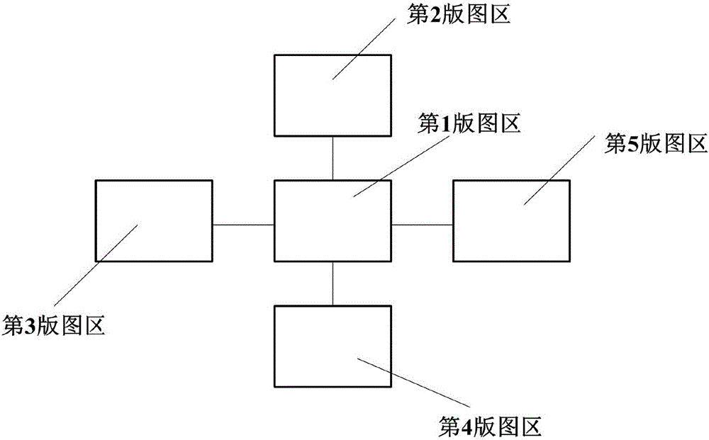
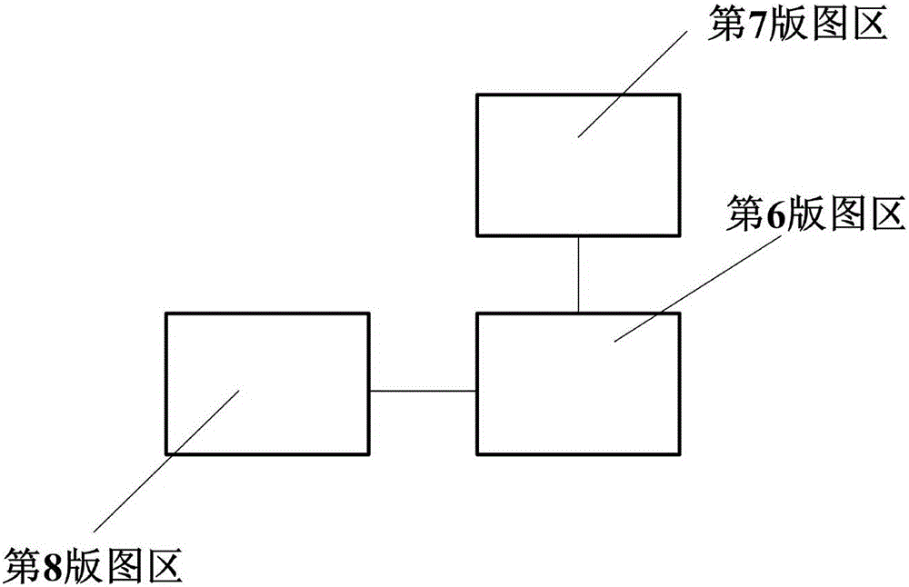
[0030] In an embodiment of the present invention, a sensor circuit layout structure for measuring clamping force includes: wireless data transmission circuit layout ( figure 1 ) and wireless data receiving circuit layout ( figure 2 ) consists of two main bodies.

[0031] Such as figure 1 As shown, the wireless data transmission circuit layout consists of the main controller module in the first layout area, the power supply module in the second layout area, the wireless communication transmission module in the third layout area, the data signal conditioning module in the fourth layout area and the third layout area. 5 The speed measurement module in the layout area. The 1st and 2nd layout areas are connected to all other layout areas, the 3rd layout area is connected to the 1st and 2nd layout areas, the 4th layout area is connected to the 1st and 2nd layout areas, and the 5th layout area is connected to the 1st and 2nd layout areas connected.

[0032] Embodiment, wireless ...


PUM


Abstract

The invention discloses a circuit layout structure of a wireless data transmitting-receiving sensor used for measuring clamping force of a chuck. The circuit layout structure is composed of a wireless data receiving part and a wireless data transmitting part. When the clamping force of the chuck is stressed to change, a resistance strain diaphragm deforms, and voltage on a corresponding resistor is made to change; since the change is small, a strain electrical bridge is adopted, a signal is amplified through an amplifying circuit, and then the signal is transmitted to a post-processing circuit, an A/D converter and a controller; and finally a wireless transmitting module transmits the signal to a wireless receiving module through a wireless communication antenna. The wireless receiving module transmits received data to an upper computer for data analyzing and processing through a USB communication protocol. Compared with the prior art, the circuit layout structure of the wireless data transmitting-receiving sensor used for measuring the clamping force of the chuck achieves high-precision acquisition of clamping force data based on the integrated circuit design technology, and has the advantages of being small in size and precise in data transmitting and receiving.

Description

technical field [0001] The invention relates to the technical field of integrated circuit design, and particularly designs a circuit layout structure of a sensor for measuring the clamping force of a chuck. Background technique [0002] With the increase of the spindle speed of modern turning machining centers, the clamping force of the chuck has become an important issue affecting machining. This is because when the chuck rotates at a high speed, the centrifugal force causes the clamping force to gradually decrease in a parabolic pattern with the increase of the rotational speed. When the clamping force drops to a certain critical value or even drops to zero, it will cause the workpiece to fly out and cause serious accidents. Increase the clamping force at rest to avoid accidents. However, if the clamping force is too large, it will cause serious deformation and damage to the workpiece when clamping. [0003] At present, the static lead-type clamping force tester has bee...

Claims


Application Information

Patent Timeline
IPC IPC(8): B23Q17/00
CPCB23Q17/00
Inventor 张跃明褚迅迅杨建武
Owner BEIJING UNIV OF TECH
Why Eureka
Try Eureka