Grinding system and method for differential case blank

A differential and housing technology, applied in the direction of grinding feed motion, grinding workpiece support, grinding machine parts, etc., can solve the problem that product quality is difficult to guarantee, safety is not guaranteed, and processing cannot be guaranteed. Accuracy and other issues, to achieve the effect of compact structure, saving space and improving the level of production automation

Active Publication Date: 2018-04-24
JIANGSU UNIV OF SCI & TECH
View PDF6 Cites 2 Cited by
  • Summary
  • Abstract
  • Description
  • Claims
  • Application Information

AI Technical Summary

Problems solved by technology

[0003] At present, the grinding process of the blank of the differential case 1 is relatively scattered. It is necessary to grind the large and small two end faces on the end grinding machine first, and then disassemble the workpiece to the cylindrical grinding machine for re-clamping and then grind each outer surface. After the round and cylindrical grinding is completed, the workpiece is removed and transported to the special-shaped surface grinder for the third clamping to grind the special-shaped surface. This grinding method has the following disadvantages: 1. The clamping process is completed manually by the worker , the labor intensity is high, the production efficiency is low, and the safety cannot be guaranteed; 2. In the whole grinding process, multiple clamping is required, and the production cycle is long; 3. The various processes of the whole grinding process are relatively scattered, occupying The production area is large; 4. The level of automation is low; 5. Multiple clamping cannot guarantee the processing accuracy, and the product quality is difficult to guarantee

Method used


Image

  • Grinding system and method for differential case blank
  • Grinding system and method for differential case blank
  • Grinding system and method for differential case blank

Examples


Embodiment Construction

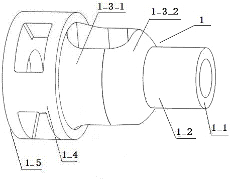
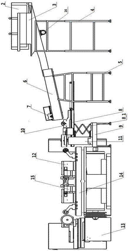
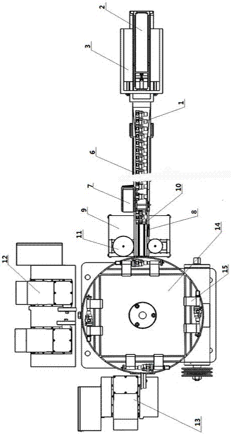
[0042] Such as Figure 2-3, a grinding system for a differential housing blank according to the present invention includes a bucket-shaped warehouse support frame 4 installed on the ground, and a bucket-shaped warehouse 3 is supported above the bucket-shaped warehouse support frame 4. Vibrator 16 is installed in the bottom of shape storehouse 3, and cuboid material storage box 2 is placed above bucket-shaped storehouse 3. On the ground on the left side of the bucket-shaped warehouse support frame 4, the material storage tank support frame 5 is fixedly installed, and the top of the material storage tank support frame 5 supports the material storage tank 6. The right end inlet of groove 6 is connected with the left end outlet of bucket-shaped storehouse 3, and dial mechanism 7 is installed in the left end outlet position of storage tank 6. On the ground on the left side of material storage tank support frame 5, end surface grinding machine support platform 9 is fixedly installe...


PUM


Abstract

The invention discloses a grinding system and method for a blank of a shell of a differential mechanism. A vibrator is arranged at the bottom of a hopper-shaped bin, a storage box can be placed on the upper part of the inside of the hopper-shaped bin, an outlet of the left end of the hopper-shaped bin is connected with an inlet of the right end of a storage groove, a drive plate mechanism is arranged at an outlet of the left end of the storage groove, a sliding table is arranged below the outlet of the left end of the storage groove, a first clamping mechanism capable of sliding along the sliding table in the left-right direction is arranged on the sliding table and is fixedly connected with the left end of a piston of a steam cylinder of the sliding table, a shear type lifter is arranged below the sliding table, an end surface grinding machine is arranged on the left side of the shear type lifter, and a rotary working table is arranged on the ground of the left side of a grinding machine supporting table; four second clamping mechanisms which are the same are uniformly arranged on a circular table board of the rotary working table in the peripheral direction; a cylindrical grinding machine is arranged on the rear side of the rotary working table; a grinding machine for a special-shaped surface is arranged on the left side of the rotary working table. Two end surfaces and the outer surface of the shell of the differential mechanism are ground automatically, and automatic level of production, production efficiency and quality of products are improved.

Description

technical field [0001] The invention belongs to the field of mechanical processing, and in particular relates to a system for transporting and clamping a differential housing blank and grinding both end surfaces and outer surfaces of the differential housing. Background technique [0002] Such as Figure 1-2 Shown is the differential case, the differential case 1 has a cylindrical large end and a small end, the large end and the small end are sequentially connected with a continuous outer circular body part and a special-shaped part, the large end and the small end outer circle The central axes of the body part and the profiled part are both collinear. When processing the differential case, it is necessary to make the small end face 1_1 of the differential case, the large end face 1_5, the outer circle of the small end 1_2, the outer circle of the big end 1_4, the outer circle 1_3_1 of the outer circle part, and the outer circle of the special-shaped part. The special-shape...

Claims


Application Information

Patent Timeline
Patent Type & Authority Patents(China)
IPC IPC(8): B24B27/00B24B41/00B24B41/06
CPCB24B27/0023B24B27/0069B24B27/0076B24B41/005B24B41/06
Inventor 张胜文王永霞徐江敏张辉
Owner JIANGSU UNIV OF SCI & TECH
Why Eureka
Try Eureka