Liquid nitrogen zero-loss biology sample low-temperature storage device

A biological sample and low-temperature storage technology, which is applied in biological packaging, household refrigeration equipment, packaging, etc., can solve the problems of unsuitable places without liquid nitrogen supply, complicated and cumbersome maintenance work, and interference with the operator's line of sight, so as to achieve simple maintenance, Avoid mutual pollution and achieve the effect of zero loss

Active Publication Date: 2016-11-09
HEFEI INSTITUTES OF PHYSICAL SCIENCE - CHINESE ACAD OF SCI
View PDF10 Cites 29 Cited by
  • Summary
  • Abstract
  • Description
  • Claims
  • Application Information

AI Technical Summary

Problems solved by technology

[0004] (1) In the prior art, even small and medium-sized biological storage tanks with good thermal insulation measures consume a few liters to more than ten liters of liquid nitrogen per day, and the liquid nitrogen filled by them usually takes a few days to a few weeks. It will be exhausted, so it is necessary to replenish liquid nitrogen in time before the liquid nitrogen is exhausted, otherwise the internal low temperature environment will be destroyed, that is to say, the existing small and medium-sized biological storage tanks need to frequently replenish liquid nitrogen, maintenance The work is complicated and tedious, not suitable for places without liquid nitrogen supply
[0005] (2) When the existing small and medium-sized biological storage tanks open the lid to access biological samples, the liquid nitrogen inside will directly contact with the atmosphere, causing the liquid nitrogen to evaporate rapidly, which not only increases the consumption of liquid nitrogen, but also A large amount of fog when liquid nitrogen evaporates will greatly interfere with the operator's sight

Method used


Image

  • Liquid nitrogen zero-loss biology sample low-temperature storage device

Examples


Embodiment approach

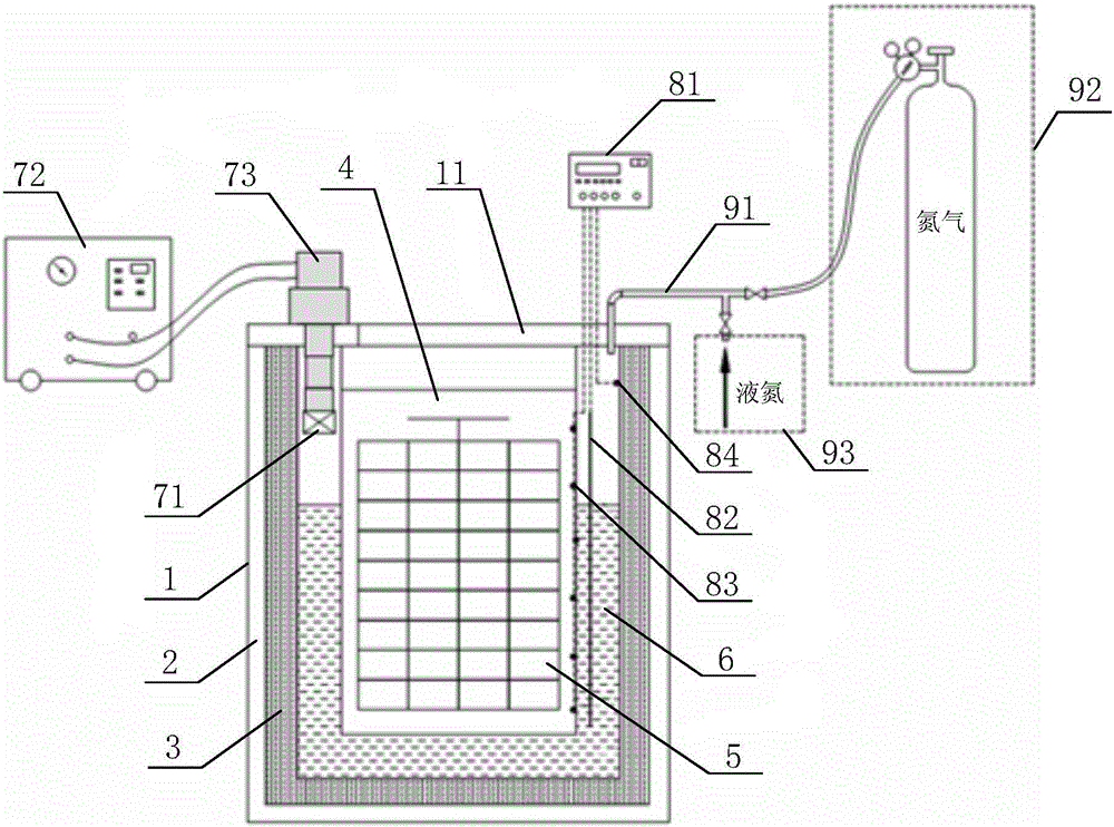
[0023] (1) The cylinder wall of the storage cylinder is preferably composed of the outer cylinder 1, the heat insulation layer 3 arranged in the outer cylinder 1, and the vacuum layer 2 arranged between the outer cylinder 1 and the heat insulation layer 3, so as to avoid the The contained liquid nitrogen 6 leaks heat through the storage cylinder wall. In practical applications, the storage cylinder may be a cylinder or a square cylinder, but is preferably a cylinder.

[0024] (2) When the top cover 11 is closed, the heat conduction liner 4 is completely in the storage cylinder, and the lower part of the heat conduction liner 4 is immersed in the liquid nitrogen 6, so that the temperature of the liquid nitrogen 6 can be transferred to the heat conduction liner 4 , and form a low-temperature environment in the heat-conducting liner 4 for preserving the biological sample 5 . When the top cover 11 is opened, the biological sample 5 can be taken out from the heat conduction liner ...


PUM


Abstract

The invention discloses a liquid nitrogen zero-loss biology sample low-temperature storage device which comprises a storage cylinder provided with a top cover (11), a heat-conducting inner container (4) and liquid nitrogen refrigerating equipment. The wall of the storage cylinder comprises an outer cylinder (1), a vacuum layer (2) and a heat-insulating layer (3). The heat-insulating layer (3) is arranged in the outer cylinder (1). The vacuum layer (2) is arranged between the outer cylinder (1) and the heat-insulating layer (3). Liquid nitrogen (6) is contained in the storage cylinder. The heat-conducting inner container (4) is soaked in the liquid nitrogen (6). A biology sample (5) is arranged in the heat-conducting inner container (4). The liquid nitrogen refrigerating equipment comprises a condensing heat exchanger (71) and a refrigerator (72). The condensing heat exchanger (71) is arranged between the heat-insulating layer (3) and the heat-conducting inner container (4). A refrigerating head (73) of the refrigerating machine (72) is connected with the condensing heat exchanger (71). The situation that in the running process, a large amount of cool air flows out is avoided, the liquid nitrogen zero loss is achieved, liquid nitrogen does not need to be supplemented, and the device is easy to maintain and suitable for places where no liquid nitrogen is supplied.

Description

technical field [0001] The invention relates to the field of biological cryopreservation, in particular to a low-temperature storage device for liquid nitrogen zero-loss biological samples. Background technique [0002] The research and development of modern biomedicine are inseparable from biological cryopreservation technology. Low temperature can inhibit the biochemical activities of organisms (including but not limited to enzymes, cells, platelets, semen, tissues and organs, plant seeds, genes, etc.) and reduce their metabolic rate, so that the organisms can be preserved for a long time. And the lower the storage temperature, the longer the storage time. Experiments have shown that after the biological cells have been cryopreserved in liquid nitrogen at -196°C for many years, no biochemical and functional changes have been found in the rewarmed biological cells. Therefore, biological cryopreservation technology can realize the long-term safe preservation of organisms, ...

Claims


Application Information

Patent Timeline
Patent Type & Authority Applications(China)
IPC IPC(8): B65D81/18B65D81/24B65D81/38B65D85/50
CPCB65D81/18B65D81/24B65D81/3806B65D85/50
Inventor 张启勇朱志刚陈喆华陆小飞成安义吴克平
Owner HEFEI INSTITUTES OF PHYSICAL SCIENCE - CHINESE ACAD OF SCI
Why Eureka
Try Eureka