
Secondary utilization method and structure for water drained from blind ditch of external wall of deep foundation pit bottom plate

A technology for deep foundation pits and exterior walls, applied in drainage structures, infrastructure engineering, waterway systems, etc., can solve problems affecting foundation construction, achieve fast construction, solve foundation pit seepage problems, and ensure construction quality and construction period

Inactive Publication Date: 2016-11-09
CHINA CONSTR FOURTH ENG DIV
View PDF4 Cites 4 Cited by
  • Summary
  • Abstract
  • Description
  • Claims
  • Application Information

AI Technical Summary

Problems solved by technology

High-rise and ultra-high-rise buildings must adopt deep foundation pits, and in the construction process of deep foundation pits, in many cases, although the groundwater has dropped below the elevation of the base, there is still a small amount of water seepage in the base or surrounding areas. Seriously affect the construction of the foundation. If the traditional foundation pit dewatering method is continued, the small amount of seepage water will not be completely discharged

Method used


Image

  • Secondary utilization method and structure for water drained from blind ditch of external wall of deep foundation pit bottom plate
  • Secondary utilization method and structure for water drained from blind ditch of external wall of deep foundation pit bottom plate
  • Secondary utilization method and structure for water drained from blind ditch of external wall of deep foundation pit bottom plate

Examples


Embodiment Construction

[0017] In order to make the purpose, technical solution and advantages of the present invention clearer, the present invention will be further described in detail below in conjunction with the accompanying drawings and embodiments.

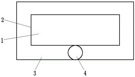
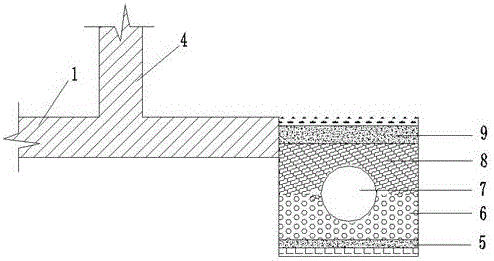
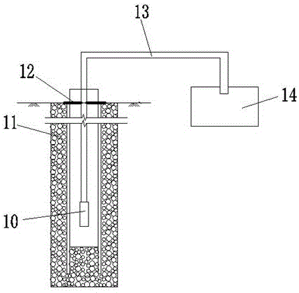
[0018] Embodiment of the present invention: a method for secondary utilization of blind ditch drainage on the outer wall of the deep foundation pit floor. The method is to set a blind ditch with a drainage slope of 2% on the outside of the outer wall of the deep foundation pit bottom plate, and at the same time, the blind ditch has the lowest base elevation. Dig a water collecting well at the place, connect the blind ditch with the water collecting well, and finally place a water pump in the water collecting well, use this water pump to pump the water in the water collecting well to the reservoir on the ground for storage, for washing hands and watering flowers And so on, in order to achieve the purpose of secondary use.

[0019] see Figure 1~3 ...


PUM


Abstract

The invention discloses a secondary utilization method and structure for water drained from a blind ditch of an external wall of a deep foundation pit bottom plate. The structure comprises the deep foundation pit bottom plate and the external wall, wherein a blind ditch is formed in the outer side of the external wall; a water collecting well is excavated at the lowest part of the foundation base elevation of the blind ditch which is enabled to be connected with the water collecting well; and finally, a water pump is placed in the water collecting well and is connected with an external water storage pond through a drain pipe. Compared with the traditional foundation pit dewatering method, a blind ditch and water collecting well dewatering method adopted by the invention has the advantages that the foundation pit water seepage problem can be thoroughly solved, the construction quality and period are ensured, and the construction cost is reduced; and meanwhile, water in the water collecting well of a deep foundation pit is pumped into a ground water storage pond by using the water pump and is secondarily utilized, so that the short water resource is indirectly saved and protected. Therefore, the secondary utilization structure is simple in structure, high in construction speed, safe and reliable, the foundation pit water seepage problem is thoroughly solved, and meanwhile, due to the adoption of the measures that the water in the deep foundation pit is drained and is collected for secondary utilization, the aim of saving water resources is achieved.

Description

technical field [0001] The invention relates to a method and structure for secondary utilization of blind ditch drainage on the outer wall of the bottom plate of a deep foundation pit, and belongs to the technical field of building construction. Background technique [0002] At present, with the growing economy of our country, the rapid advancement of the urbanization process and the shortage of land resources, high-rise and super high-rise buildings have become a basic trend in the development of urban buildings. High-rise and ultra-high-rise buildings must adopt deep foundation pits, and in the construction process of deep foundation pits, in many cases, although the groundwater has dropped below the elevation of the base, there is still a small amount of water seepage in the base or surrounding areas. Seriously affect the construction of the foundation, if continue to adopt the traditional foundation pit dewatering method, this small amount of seepage water will not be co...

Claims


Application Information

Patent Timeline
Patent Type & Authority Applications(China)
IPC IPC(8): E02D19/20E03F5/10E03F5/22
CPCE02D19/20E03F5/10E03F5/22
Inventor 苏伟刘辉岳巍叶国昌孙永国
Owner CHINA CONSTR FOURTH ENG DIV
Learn More