

Integrated solar intelligent constant-temperature ecological curtain wall system and temperature control method
An ecological curtain wall, solar energy technology, applied in air conditioning systems, heating and ventilation control systems, heating and ventilation safety systems, etc., can solve the problems of increasing semiconductor refrigeration power consumption, increasing refrigeration function, heat loss, etc., to improve fire safety. performance, loss prevention, and the effect of improving energy-saving effects
- Summary
- Abstract
- Description
- Claims
- Application Information
AI Technical Summary
Problems solved by technology
Method used
Image

Examples
Embodiment 1
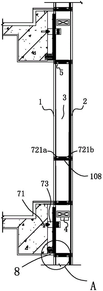
[0043] Embodiment 1: An integrated solar sensor intelligent constant temperature ecological curtain wall system, including mechanical parts and circuit parts; wherein the mechanical parts are as follows figure 1 shown, including unitized modules,
[0044] The unitary module is installed around the building through the installation structure. The unitary module includes the inner glass curtain wall 1, the outer glass curtain wall 2, and also includes a solar power generation device. The solar power generation device includes a solar panel, a controller, a battery and an inverter; The solar panel is solar glass arranged on the outer glass curtain wall. In addition, since the solar power generation device belongs to the prior art, it is not specifically described in this patent. The solar power generation device provides electricity for the curtain wall system. The inner glass curtain wall 1 is single-layer glass and the outer glass curtain wall 2 is double-layer glass. A hollow ...
Embodiment 2
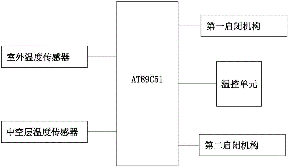
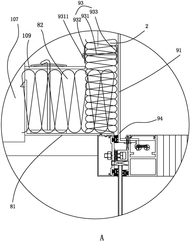
[0065] Embodiment two, see Figure 5 As shown, the difference from Embodiment 1 is that the air outlet 22 and the air inlet 21 are provided on the second beam 721b; the air inlet 21 and the air outlet 22 are opened and closed by the first opening and closing mechanism, and the upper and lower curtain wall layers Blocked by the fireproof sealing unit 8; the first beam 721a is provided with a vent 11, and the vent 11 is provided with a second opening and closing mechanism for opening or closing. The second opening and closing mechanism is also the electric shutter 6. When the outdoor temperature sensor 51 detects that the outdoor temperature signal To is equal to the preset temperature Tx, the single-chip microcomputer controls the electric shutter 6 to open the vent 11 to ventilate the room.
[0066] Also, see figure 2 , it is also possible to couple an outdoor temperature sensor 51 at the input end of the single-chip microcomputer, and couple the first opening and closing me...
PUM
 Abstract
Description
Claims
Application Information