System of low-temperature regeneration, drying and dehumidification for low-dew point drying room

A zone and wheel technology, applied in the field of drying and dehumidification devices, can solve the problems of high energy consumption and high initial cost, and achieve the effect of reducing emissions

Active Publication Date: 2016-11-09
SEIBU GIKEN CO LTD
View PDF12 Cites 12 Cited by
  • Summary
  • Abstract
  • Description
  • Claims
  • Application Information

AI Technical Summary

Problems solved by technology

However, since it has a cooler and three regenerators, the energy consumption of

Method used


Image

  • System of low-temperature regeneration, drying and dehumidification for low-dew point drying room
  • System of low-temperature regeneration, drying and dehumidification for low-dew point drying room
  • System of low-temperature regeneration, drying and dehumidification for low-dew point drying room

Examples


no. 1 example

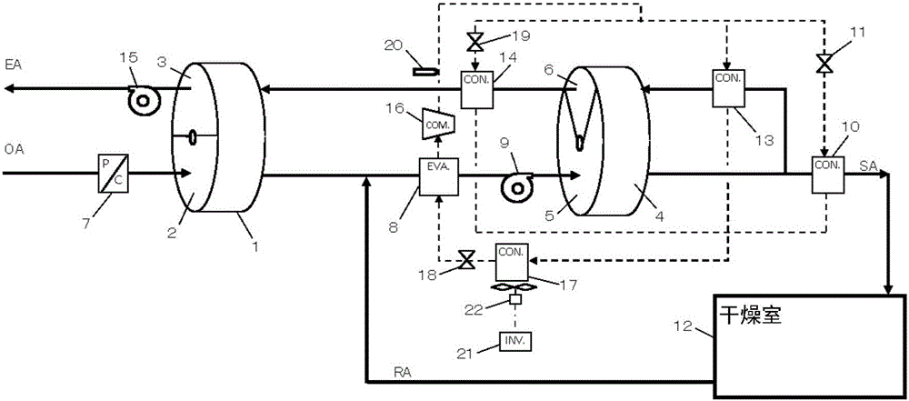
[0055] figure 1 It is a figure which shows the dehumidification apparatus of 1st Example of this invention. 1 is the first desiccant wheel, which is divided into the adsorption area 2 and the regeneration area 3. 4 is the second desiccant wheel, which is also divided into the adsorption area 5 and the regeneration area 6.

[0056] Reference numeral 7 denotes a first cooler (pre-cooler) for cooling and dehumidifying the outside air OA. That is, it is used to cool the air below the dew point of the outside air. The air passing through the first cooler 7, under the action of the first blower 9, after passing through the adsorption area 2 of the first dehumidification wheel 1, passes through the second cooler 8 (intercooler) and the second dehumidification wheel 4 Moreover, the temperature is adjusted by the first heater 10 (post-heater), and the air is supplied to the drying chamber 12 which is the supply destination of the dry air.

[0057] The return air RA from the drying c...

no. 2 example

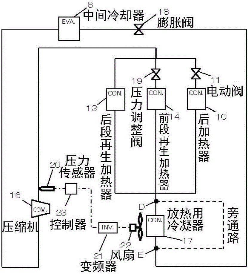
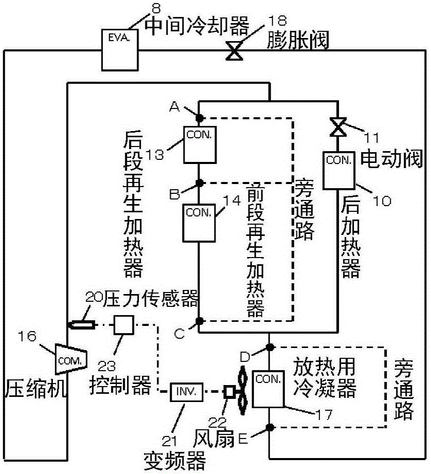
[0070] Figure 5 It is a figure which shows the dehumidification apparatus of the 2nd Example of this invention. In addition, the equipment structure of the dehumidification device and figure 1 The same as the first embodiment. also, Figure 6 is a diagram showing the flow of the refrigerant in the second embodiment. and figure 2 The refrigerant flow similarly, Figure 6The heat pump circuit of the embodiment is composed of compressor 16, evaporator for second cooler 8, 4 for first heater 10, second heater 13, third heater 14 and condenser 17 for heat release However, the evaporator for the first cooler 7 and the evaporator for the second cooler 8 are arranged in parallel. In addition, as a countermeasure against unstable operation due to low external air load and low refrigerant pressure as in winter, in order to enable stable operation of the refrigerant flow, the evaporator inlet from the condenser inlet side to the first cooler 7 Between the HIs on the side, a hot ...


PUM


Abstract

The invention provides a dehumidification device which applies a heat pump which can supply low-dew point air even if a regeneration temperature is as low as 50 DEG. The device provided by the invention comprises a first dehumidification turning wheel and a second dehumidification turning wheel, wherein an external gas is made to pass an adsorption area of the first dehumidification turning wheel after being cooled and dehumidified by a first cooler, the air which passes the adsorption area of the first dehumidification turning wheel is made to pass a second cooler and an adsorption area of the second dehumidification turning wheel and supplied to a drying room as supply air; and returning air from the drying room is mixed with the air which passes the adsorption area of the first dehumidification turning wheel, the air which passes the adsorption area of the second dehumidification turning wheel is partially shunted, heated by a second heater and then made to pass a regeneration area of the second dehumidification turning wheel, and the air which passes the regeneration area of the second dehumidification turning wheel is heated by a third heater and made to pass a regeneration area of the first dehumidification turning wheel.

Description

technical field [0001] The present invention relates to a dry dehumidification device which utilizes a dehumidification rotor and a heat pump and can supply air with a low dew point even if the regeneration temperature is low. Background technique [0002] Recently, as the demand for lithium batteries has increased, their production has continued to expand. Lithium batteries, since lithium used as a raw material reacts with moisture in the air, the performance of the produced lithium batteries deteriorates due to the reaction. Therefore, the production line of lithium batteries needs to be kept dry. As a method of maintaining a dry state, there are: a method of purging the production plant with dry nitrogen; a method of using a dehumidification device using a dehumidification rotor equipped with silica gel or other moisture adsorption methods. agent. [0003] As lithium batteries are widely used in electric vehicles, hybrid vehicles and other vehicles, the scale of produc...

Claims


Application Information

Patent Timeline
IPC IPC(8): F24F3/14F24F11/76
CPCF24F3/14F24F2003/144F24F2003/1458F24F2203/12
Inventor 江岛宽明河口和彦松尾慎
Owner SEIBU GIKEN CO LTD
Why Eureka
Try Eureka