Combined heating and cooling type method and system for copious cooling liquefied air

A technology for supplying system and liquid air, applied in the fields of thermal energy supply system and cold energy supply system, can solve the problems of energy waste, incomplete utilization of thermal energy and cold energy surplus, and achieve the effect of improving utilization rate and avoiding thermal energy loss and waste.

Inactive Publication Date: 2016-11-09
GLOBAL ENERGY INTERCONNECTION RES INST CO LTD +1
View PDF9 Cites 1 Cited by
  • Summary
  • Abstract
  • Description
  • Claims
  • Application Information

AI Technical Summary

Problems solved by technology

[0003] Therefore, the technical problem to be solved by the present invention is to overcome the technical defect of the existing liquefied air energy storage technology that the surplus of thermal energy and cold energy cannot be fully utilized, resulting in serious energy waste

Method used


Image

  • Combined heating and cooling type method and system for copious cooling liquefied air
  • Combined heating and cooling type method and system for copious cooling liquefied air

Examples


Embodiment 1

[0038] This embodiment provides a thermal energy supply method, including the following steps:

[0039] Step 1: Use electric energy to convert gaseous air into liquid air under low temperature and high pressure conditions;

[0040] Step 2: collecting the heat energy released during the conversion process of step 1;

[0041] Step 3: Use the heat energy collected in step 2 to supply heat energy.

[0042] The above steps are the core technical solution of this embodiment, generating thermal energy by compressing gaseous air into liquid air, collecting and storing the thermal energy, and supplying the collected and stored thermal energy to the thermal energy receiving end. In the existing liquefied air energy storage technology, the heat energy released in the energy storage stage is often collected and only used for heating during the gasification process of liquid air. In this embodiment, the remaining waste heat in the heat storage process is stored and used In order to suppl...

Embodiment 2

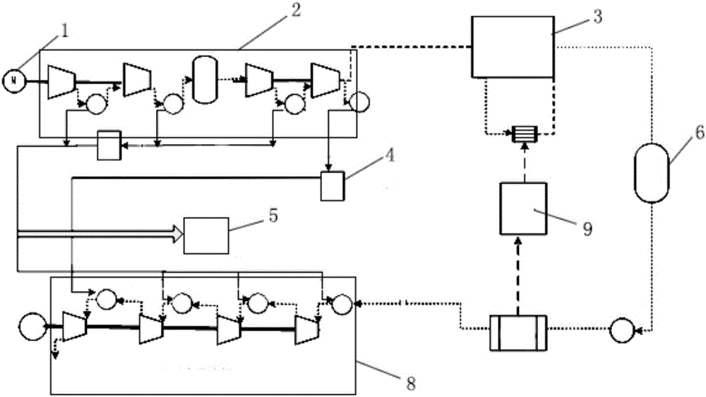
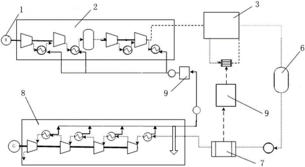
[0046] refer to figure 1 , this embodiment provides a thermal energy supply system, using the supply method described in Embodiment 1, the system includes: a motor 1, an air compressor unit 2, a liquefaction device 3, and a heat storage device 4, the motor 1 is used to drive The air compressor unit 2 and the liquefaction device 3 are used to convert gaseous air into liquid air, and the heat storage device 4 is used to collect heat energy released during the conversion process. Specifically, the air compressor unit 2 is preferably two groups, wherein the first group of air compressor unit is a low-pressure compressor unit, and the air compressed by the low-pressure compressor unit enters the air purification device, then passes through the second group of air compressor unit, and finally is liquefied Liquefaction was completed in unit 3. The heat storage device 4 can be a heat storage tank or the like, which is connected to each of the compressor units to absorb the heat energ...

Embodiment 3

[0050] This embodiment provides a cold energy supply method based on the heat energy supply method in Embodiment 1. Since the liquefied air energy storage technology is a cycle in which air is compressed into a liquid state and then expanded from a liquid state to a gas state, cold energy and heat energy The supplies are also preferably closely coupled to each other. The cold energy supply method of this embodiment includes the following steps:

[0051] Step 4: Collect the liquid air prepared in Step 1;

[0052] Step 5: Convert the Yetai air into gaseous air under high temperature and high pressure conditions, and collect the cold energy released during the conversion process;

[0053] Step 6: Use the cold energy collected in step 5 to supply cold energy.

[0054] Similar to the thermal energy supply method in Embodiment 1, in this embodiment, the cold energy generated during the liquid air vaporization process is collected, and then the collected cold energy is supplied to ...


PUM


Abstract

The invention provides a heat energy supply method, a cold energy supply method, a heat energy supply system and a cold energy supply system. The heat energy supply method comprises the following steps that 1, gaseous air is converted into liquefied air under the low-temperature high-pressure condition with electric energy; 2, heat energy released in the conversion process of the step 1 is collected; and 3, the heat energy connected through the step 2 is used for conducting heat energy supply, waste cold and waste heat which are produced through the liquefied air energy storage technology are used for conducting heat energy supply and cold energy supply, the energy utilization efficiency is improved, and wasting is avoided.

Description

technical field [0001] The invention relates to the technical field of liquefied air energy storage, in particular to a heat energy supply method, a cold energy supply method, a heat energy supply system and a cold energy supply system using liquefied air. Background technique [0002] Cryogenic liquefied air energy storage technology refers to the use of electric energy for compressed air during the low load period of the grid, and the high-pressure sealing of the air in abandoned mines, subsidence subsea gas storage tanks, caves, expired oil and gas wells or newly built gas storage wells. The energy storage method releases compressed air during the peak period to drive the steam turbine to generate electricity. The liquid air energy storage system has the advantages of large energy storage capacity, long energy storage period, small footprint and does not depend on geographical conditions. During energy storage, the electric energy compresses, cools and liquefies the air, ...

Claims


Application Information

Patent Timeline
Patent Type & Authority Applications(China)
IPC IPC(8): F25J5/00F01K27/02
CPCF25J1/0012F25J1/0045F25J1/0201F25J1/0242F25J1/0251F25J2205/24F25J2230/04F25J2240/90F25J5/00F01K27/02
Inventor 宋洁王乐赵波徐桂芝邓占锋杨岑玉金翼汤广福宋鹏翔胡晓李志远梁立晓
Owner GLOBAL ENERGY INTERCONNECTION RES INST CO LTD
Why Eureka
Try Eureka