Transformer station secondary side electric energy measuring system and method

An electric energy measurement, secondary side technology, applied in the measurement of electrical variables, non-electrical signal transmission systems, measurement devices, etc., can solve the problem of inaccurate measurement values, inability to maintain synchronization, low accuracy and reliability of electric energy measurement in substations, etc. problems, to achieve the effect of improving accuracy and reliability, and accurate measurement values

Inactive Publication Date: 2016-11-09
DONGGUAN LIANZHOU INTPROP OPERATION MANAGEMENT CO LTD
View PDF8 Cites 4 Cited by
  • Summary
  • Abstract
  • Description
  • Claims
  • Application Information

AI Technical Summary

Problems solved by technology

[0004] For this reason, the technical problem to be solved by the present invention is that the measurement value of the secondary side electric energy measurement system used in the substation in the prior art is inaccurate and unable to maintain synchronization, which eventually leads to low accuracy and reliability of the electric energy measurement of the substation, thus proposing A substation secondary side electric energy measurement system and its measurement method

Method used


Image

  • Transformer station secondary side electric energy measuring system and method
  • Transformer station secondary side electric energy measuring system and method

Examples


Embodiment 1

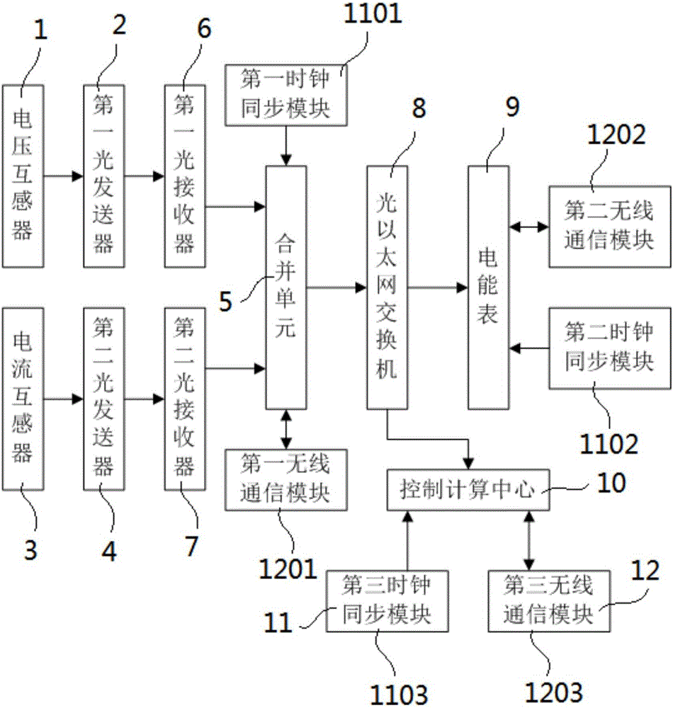
[0034] Such as figure 1 As shown, the secondary side electric energy measurement system of the substation of the present invention includes:

[0035] The voltage transformer 1 is connected with a first optical transmitter 2.

[0036] The current transformer 3 is connected to the second optical transmitter 4.

[0037] The merging unit 5 is respectively connected with a first optical receiver 6 and a second optical receiver 7, the first optical receiver 6 is in communication connection with the first optical transmitter 2, and the second The optical receiver 7 is in communication connection with the second optical transmitter 4.

[0038] The optical Ethernet switch 8 has a first end connected to the merging unit 5. In this embodiment, the optical Ethernet switch 8 and the merging unit 5, the electric energy meter 9, and the computing control center 10 adopt optical fiber communication.

[0039] The electric energy meter 9 is connected to the second end of the optical Ethernet switch 8. ...

Embodiment 2

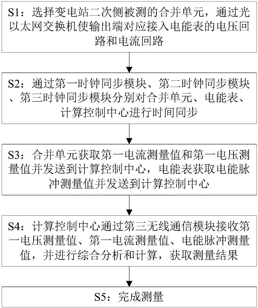
[0045] Such as figure 2 As shown, the secondary side electric energy measurement method of the substation of the present invention includes the following steps:

[0046] S1: Select the combined unit 5 to be tested on the secondary side of the substation, and connect the output end to the voltage loop and current loop of the electric energy meter 9 through the optical Ethernet switch 8.

[0047] S2: Perform time synchronization on the merging unit 5, the electric energy meter 9, and the computing control center 10 through the first clock synchronization module 1101, the second clock synchronization module 1102, and the third clock synchronization module 1103, respectively.

[0048] S3: The voltage transformer 1 performs measurement to obtain the first voltage measurement value, and sends it to the merging unit 5 through the first optical transmitter 2, and the current transformer 3 performs measurement to obtain the first current measurement value, and passes the second optical trans...


PUM


Abstract

The invention discloses a transformer station secondary side electric energy measuring system comprising a voltage transformer, a current transformer, a first optical transmitter, a second optical transmitter, a first optical receiver, a second optical receiver, a merging unit, an optical Ethernet switch, an electric energy meter, a computation control center, a clock synchronization module, and a wireless communication module. The transformer station secondary side electric energy measuring system solves a problem that an intelligent transformer station merging unit is long in distance and unsafe in field detection, may synchronously measure electric energy of merging units distributed at different sites and branch electric energy meters, achieves accurate measured values and maintains synchronization, enhances the electric energy metering accuracy and reliability of the transformer station, and is convenient, concise, efficient, and safe.

Description

Technical field: [0001] The invention belongs to the technical field of electric energy measurement, and specifically relates to a secondary side electric energy measurement system and a measurement method of a substation. Background technique: [0002] In recent years, with the maturity of substation intelligent switches, photoelectric transformers, online status detection of primary operating equipment, substation operation training simulation technology, and the development and application of computer telling networks in real-time systems, information collection for substations It provides a theoretical and material basis for the realization of digital processing in aspects such as transmission, measurement, measurement, and protection. The development of optoelectronics, microelectronics, computer and communication technology has made various intelligent devices in substations have the characteristics of digitalization, intelligence and low power consumption. The merging uni...

Claims


Application Information

Patent Timeline
Patent Type & Authority Applications(China)
IPC IPC(8): G01R22/10G01R22/06G08C17/02G08C23/06
CPCG01R22/10G01R22/063G08C17/02G08C23/06
Inventor 王文庆
Owner DONGGUAN LIANZHOU INTPROP OPERATION MANAGEMENT CO LTD
Why Eureka
Try Eureka