Automatic focusing microscopic imaging system for planet surface material in-situ detection

A microscopic imaging and planetary surface technology, applied in the field of optical engineering, can solve problems such as low efficiency, long time consumption, and many images, and achieve high integration and eliminate the effect of positioning accuracy

Inactive Publication Date: 2016-11-09
XI'AN INST OF OPTICS & FINE MECHANICS - CHINESE ACAD OF SCI
View PDF4 Cites 1 Cited by
  • Summary
  • Abstract
  • Description
  • Claims
  • Application Information

AI Technical Summary

Problems solved by technology

[0003] When microscopic imaging loads obtain clear images, the traditional method is to image the samples to be tested at different object distances, and then select clear images from a series of images collected. This method collects more images and takes more time. long, inefficient

Method used


Image

  • Automatic focusing microscopic imaging system for planet surface material in-situ detection
  • Automatic focusing microscopic imaging system for planet surface material in-situ detection

Examples


Embodiment Construction

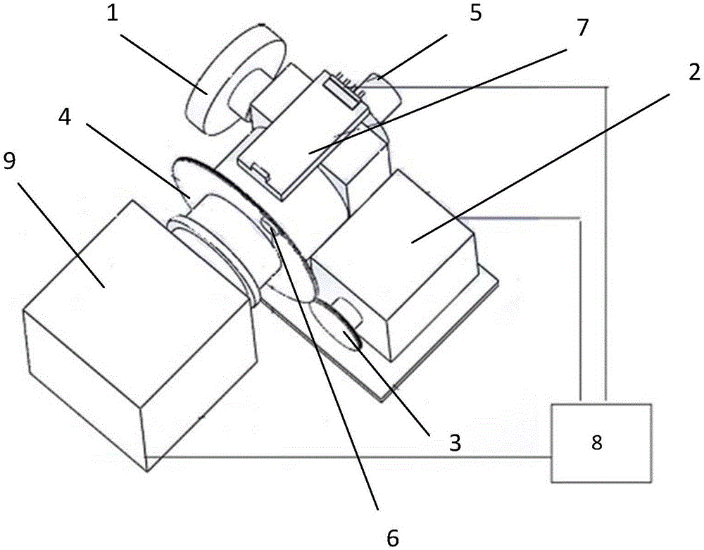
[0017] See figure 1 , The present invention is an automatic focusing microscopic imaging system device for detecting planetary surface substances in place. The whole system includes: an illumination unit, a microscopic optical imaging unit, an image acquisition unit (CCD camera 9), a focusing transmission unit (drive wheel, Driven wheel, magnetic beads, motor, Hall sensor), upper computer unit. When this device performs microscopic imaging of the tested sample, the host computer calculates the in-focus position by judging the image clarity, and sends corresponding instructions to control the imaging system to reach the designated position, and quickly obtain a clear microscopic image of the tested object .

[0018] The illumination part and the microscopic optical imaging part of the automatic focusing device share a common optical path. The light emitted by the LED illuminating light source 1 illuminates the beam splitter through the illuminating condenser, and illuminates the ...


PUM


Abstract

The invention provides an automatic focusing microscopic imaging system for planet surface material in-situ detection. The automatic focusing microscopic imaging system comprises a lighting unit, a microscopic imaging unit, an image acquisition unit, a focusing transmission unit and an upper computer unit; the lighting unit and the microscopic imaging unit are located in the same optical path; the microscopic imaging unit includes a microscope objective lens and a microscope lens barrel; the focusing transmission unit is a gear external-engagement transmission device; the arrangement direction of the focusing transmission unit is perpendicular to the lighting unit; the focusing transmission unit converts the transmission of gears to the movement of the microscope lens barrel; the image acquisition unit and the microscope lens barrel are in the same optical path; the image acquisition unit is connected with the focusing transmission unit; and the upper computer unit carries out definition judgment on an acquired image and controls the whole system to make the same in a focusing state. With the automatic focusing microscopic imaging system of the invention adopted, definition judgment can be carried out on the image of a sample to be detected; a focusing position can be found out quickly through a fitting a focusing function, and therefore, the speed and precision of focusing can be improved. Unitization design is adopted, so that the automatic focusing microscopic imaging system has the advantages of small size, strong function and so on.

Description

Technical field [0001] The invention belongs to the field of optical engineering, and in particular relates to an automatic focusing microscopic imaging device, which uses an image sharpness evaluation function to quickly realize a focusing process and obtain a clear microscopic image of a sample to be tested. Background technique [0002] In the field of deep space exploration, the microscopic imaging system is used as the optical load for in-situ detection. By imaging the surface soil and rock samples of planetary geology, according to the characteristics of image size, texture, color, etc., the topography and geomorphology can be recognized from a microscopic perspective, and then judged Soil element composition, mineral composition analysis, etc. Such as the microscopic imager (MI) carried by the US "Opportunity", the optical microscope (OM) carried by the "Phoenix" Mars lander, the MAHLI camera carried by the "Curiosity", and the ESA "ExoMars" carry MicroOmega hyperspectral...

Claims


Application Information

Patent Timeline
Patent Type & Authority Applications(China)
IPC IPC(8): G02B21/36G02B21/24G02B21/06
CPCG02B21/06G02B21/244G02B21/367
Inventor 陶金有葛伟王渊博杨建峰
Owner XI'AN INST OF OPTICS & FINE MECHANICS - CHINESE ACAD OF SCI
Why Eureka
Try Eureka