DC composite tower sulfur dioxide treatment system

A sulfur dioxide and treatment system technology, applied in the direction of gas treatment, combustion product treatment, combined devices, etc., can solve the problems that the reaction tower cannot operate, affects the desulfurization efficiency of the desulfurization tower, and is easy to block the screen holes, etc., to achieve enhanced operation reliability, The effect of saving investment costs and reducing floor space

Pending Publication Date: 2016-11-16
ANHI SHENGYUN HEAVY MACHINERY CO LTD
View PDF4 Cites 1 Cited by
  • Summary
  • Abstract
  • Description
  • Claims
  • Application Information

AI Technical Summary

Problems solved by technology

[0004] Both the DS multiphase desulfurization tower and the CST cross-flow plate tower in the prior art belong to wet desulfurization. Although they each have high desulfurization efficiency, their shortcomings are as follows: DS multiphase desulfurization tower, such as figure 1 As shown, although the desulfurization tower has a high desulfurization efficiency, it can be seen from the figure alone that the reaction liquid and the flue gas are not closed during the contact process, and there will be a small part of the gas that does not contact the reaction liquid and passes through the mist eliminator. After being discharged from the reaction tower, it affects the desulfurization efficiency of the desulfurization tower; CST through-flow plate tower, such as figure 2 As shown, due to the relatively small pores on the surface, all kinds of reaction solutions are limited, and SO 2 The reaction solution produced by the reaction cannot be used in the reaction tower, and it is easy to block the sieve holes, making the reaction tower unable to operate

Method used


Image

  • DC composite tower sulfur dioxide treatment system
  • DC composite tower sulfur dioxide treatment system
  • DC composite tower sulfur dioxide treatment system

Examples


Embodiment Construction

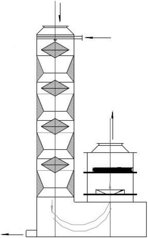
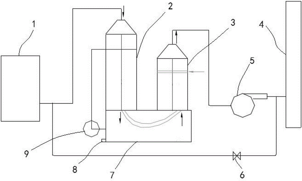
[0016] A kind of DC composite tower sulfur dioxide treatment system, such as image 3 As shown, it includes a DS multiphase desulfurization tower 2 and a CST through-flow plate tower 3; the top of the DS multiphase desulfurization tower 2 is connected to the boiler 1 through a pipeline, and the lower end of the DS multiphase desulfurization tower 2 is set on the sedimentation tank 7 and communicated with it;

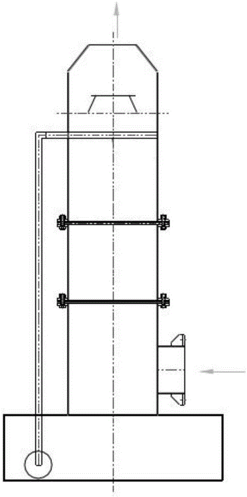
[0017] The lower end of the CST through-flow plate tower 3 is set on the sedimentation tank 7 and communicated with it; the top of the CST through-flow plate tower 3 is connected to the induced draft fan 5 through a pipeline, and the induced draft fan 5 is connected to the chimney 4 through a pipeline;

[0018] The lower part of the sedimentation tank 7 is provided with a sewage outlet 8; the middle part of the sedimentation tank 7 is connected to the upper part of the DS multiphase desulfurization tower 2 through a circulation pump 9;

[0019] On the pipeline between th...


PUM

PropertyMeasurementUnit
thicknessaaaaaaaaaa

Abstract

The invention discloses a DC composite tower sulfur dioxide treatment system. The DC composite tower sulfur dioxide treatment system comprises a DS multiphase desulphurization tower and a CST turbogrid tower, wherein the top end of the DS multiphase desulphurization tower is communicated with a boiler by virtue of a pipeline, and the lower end of the DS multiphase desulphurization tower is arranged on a settling pond and communicated with the settling pond; the lower end of the CST turbogrid tower is arranged on the settling pond and communicated with the settling pond; the top end of the CST turbogrid tower is connected with a draught fan by virtue of a pipeline, and the draught fan is communicated with a chimney by virtue of a pipeline; a sewage opening is formed in the lower part of the settling pond; the middle part of the settling pond accesses the upper part of the DS multiphase desulphurization tower by virtue of a circulating pump; and the pipelines between the draught fan and the chimney and between the boiler and the DS multiphase desulphurization tower are communicated by virtue of a circulating wind pipe. A DC composite tower solves the problem of secondary pollution caused by the emission of wet desulphurization exhaust gas carrying aerosol particles; and the DC composite tower sulfur dioxide treatment system reduces the floor occupation area when various single towers are used in serial connection, saves the investment expense and improves the system operation reliability.

Description

technical field [0001] The invention belongs to the technical field of environmental protection equipment, and relates to a DC compound tower sulfur dioxide treatment system, in particular to an integrated desulfurization technology of a DS multiphase desulfurization tower and a CTS cross-flow tray. Background technique [0002] The main component of flue gas pollutants discharged by industry is SO 2 and dust, causing serious harm to the atmospheric environment and human beings. The integrated technology of flue gas desulfurization and dust removal can be integrated into the process engineering, combining the two operating units of desulfurization and dust removal, which has high efficiency and low investment. The promotion of integrated technology of dust removal and desulfurization will improve the living environment, increase economic benefits and regional benefits Air quality plays an important role. The desulfurization system is located at the end of the flue and afte...

Claims


Application Information

Patent Timeline
Patent Type & Authority Applications(China)
IPC IPC(8): B01D53/80B01D53/50B01D53/96B01D50/00B01D47/04F23J15/04
CPCB01D47/04B01D50/00B01D53/502B01D53/504B01D53/80B01D53/96F23J15/04F23J2219/40F23J2215/20B01D2251/604B01D2251/404B01D2258/0283
Inventor 汪玉杨翠于金献王增坤张兴
Owner ANHI SHENGYUN HEAVY MACHINERY CO LTD
Why Eureka
Try Eureka