
Oil leakage prevention noise reduction energy-saving furnace core used for compression type combustion furnace

A combustion furnace, oil leakage prevention technology, applied in the burner noise control, burner, burner and other directions, can solve the problems of low fuel utilization rate, high noise, etc., to improve the utilization rate of energy, reduce noise, and improve utilization. rate effect

Inactive Publication Date: 2016-11-16
洪序明
View PDF4 Cites 0 Cited by
  • Summary
  • Abstract
  • Description
  • Claims
  • Application Information

AI Technical Summary

Problems solved by technology

[0004] The invention provides an oil-leakage-proof, noise-reducing, energy-saving furnace core for a compression-type combustion furnace to overcome the problems of high noise and low fuel utilization in the existing compression-type combustion furnace

Method used


Image

  • Oil leakage prevention noise reduction energy-saving furnace core used for compression type combustion furnace
  • Oil leakage prevention noise reduction energy-saving furnace core used for compression type combustion furnace
  • Oil leakage prevention noise reduction energy-saving furnace core used for compression type combustion furnace

Examples


Embodiment approach 1

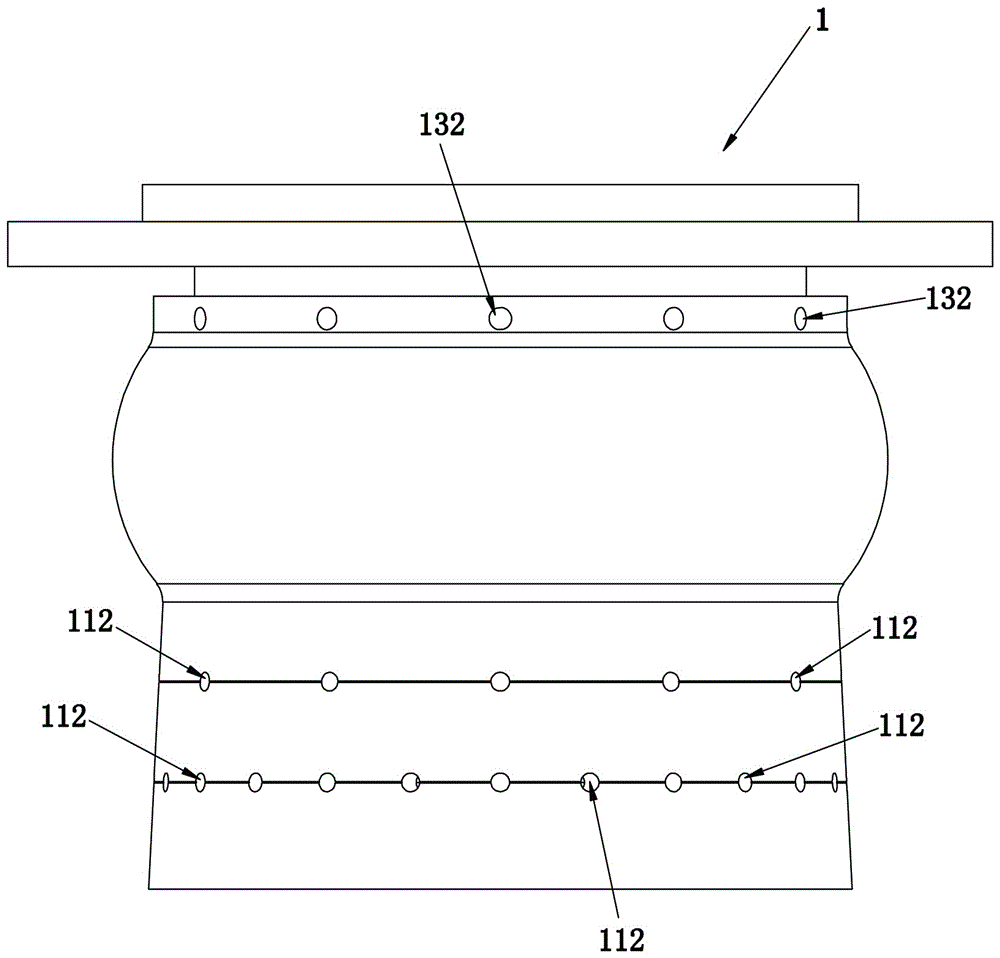
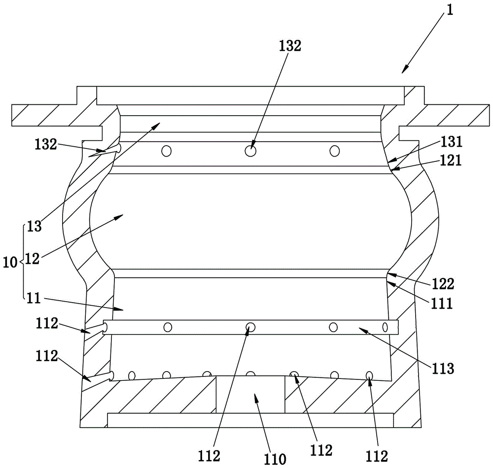
[0020] refer to figure 1 , figure 2 , an oil-leakage-proof, noise-reducing, energy-saving furnace core for compression combustion furnaces, comprising a furnace core body 1, the hollow area of ​​the furnace core body 1 being a combustion zone 10; the combustion zone 10 consists of combustion pools 11 arranged sequentially from bottom to top , an annular depression 12 and a necking area 13; the annular depression 12 is arranged around the inner wall of the furnace core body 1 . Fuel burns in the combustion pool 11 to generate flames, and the flames are ejected from the fire end of the top of the furnace core body 1 after passing through the annular depression 12 and the necking area 13 from the combustion pool 11. The concave surface of the annular depression 12 is an arc surface, the top edge 121 of the annular depression 12 is connected with the arc surface of the bottom edge 131 of the above-mentioned necking area 13, and the bottom edge 122 of the annular depression 12 is...

Embodiment approach 2

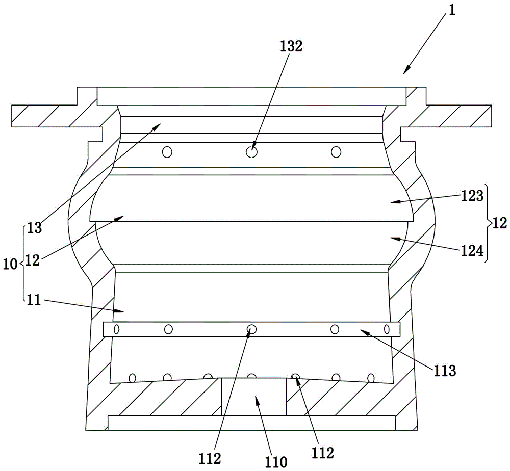
[0024] The difference between this embodiment and the first embodiment lies in the structure of the annular recess 12 . refer to image 3 , the annular depression 12 of the present embodiment is formed by an upper annular concave surface 123 and a lower annular concave surface 124, the upper annular concave surface 123 and the lower annular concave surface 124 are arc-shaped structures, and the diameter of the upper annular concave surface 123 is greater than the diameter of the lower annular concave surface 124; The top edge 121 of the upper annular concave surface 123 is transitionally connected with the bottom edge 131 of the constriction area 13 , and the bottom edge 122 of the lower annular concave surface 124 is transitionally connected with the top edge 111 of the combustion pool 11 .


PUM


Abstract

The invention relates to an oil leakage prevention noise reduction energy-saving furnace core used for a compression type combustion furnace. The oil leakage prevention noise reduction energy-saving furnace core comprises a furnace core main body. A hollow area of the furnace core main body is a combustion area. The fire outlet end of the combustion area is arranged at the top of the furnace core main body. The inner side wall of the furnace core main body is provided with an annular indentation arranged around the inner side wall of the furnace core main body. According to the oil leakage prevention noise reduction energy-saving furnace core used for the compression type combustion furnace, a good rectifying effect on flame flow can be achieved through the structure arrangement of the annular indentation, and then noise in the operation process of the combustion furnace is effectively reduced; and thus, the flame flow can rush out in a concentrated mode, and the noise is controlled and maintained at about 50 db.

Description

technical field [0001] The invention relates to a component used in a compression-type combustion furnace, in particular to an oil-leakage-proof, noise-reducing, energy-saving furnace core for a compression-type combustion furnace. Background technique [0002] The compression combustion furnace is a kind of tubular heating furnace. It blows air into the combustion pool through a fan or a compressor, ignites the fuel through an igniter, and pushes the flame out quickly under the agitation of the air. [0003] Existing compression burners mainly include a combustion pool, an oil supply mechanism, an igniter, a blast mechanism, an atomizing mechanism, and the like. The following problems exist in the existing compression burner during use: first, the noise is loud; High cost of use. Contents of the invention [0004] The invention provides an oil-leakage-proof, noise-reducing, energy-saving furnace core for a compression-type combustion furnace to overcome the problems of ...

Claims


Application Information

Patent Timeline
Patent Type & Authority Applications(China)
IPC IPC(8): F23D11/36
CPCF23D11/36F23D2210/00
Inventor 洪序明
Owner 洪序明
Learn More