All-fiber current transformer control system

A current transformer and control system technology, which is applied in the direction of converting sensor output, measuring current/voltage, and using optical devices to transmit sensing components, etc., can solve the problem of low measurement accuracy and achieve high control accuracy and meet measurement accuracy. Requirements, the effect of simple structure

Inactive Publication Date: 2016-11-16
GUILIN TRYIN TECH CO LTD
View PDF3 Cites 1 Cited by
  • Summary
  • Abstract
  • Description
  • Claims
  • Application Information

AI Technical Summary

Problems solved by technology

[0004] What the present invention needs to solve is the problem of low measurement accuracy of existing conventional electromagnetic current transformers, and provides an all-optical current transformer control system

Method used


Image

  • All-fiber current transformer control system

Examples


Embodiment Construction

[0018] The present invention will be further described below in conjunction with embodiment.

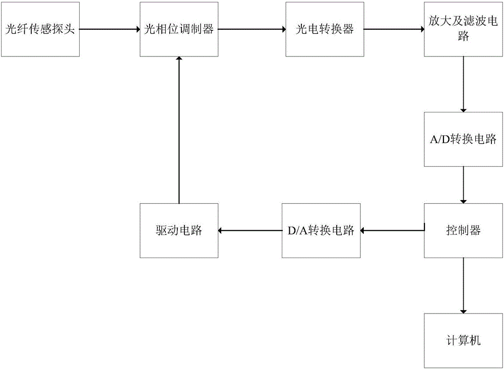
[0019] An all-fiber-optic current transformer control system, such as figure 1 As shown, it includes optical fiber sensing probe, optical phase modulator, photoelectric converter, amplification and filter circuit, A / D conversion circuit, controller circuit, computer, D / A conversion circuit and drive circuit. Optical fiber sensing probe, its structure is that the outer layer of the bare optical fiber is covered with a plastic protective sleeve to prevent damage to the optical fiber by external hard objects.

[0020] The output end of the optical fiber sensing probe is connected to the input end of the optical phase modulator; the output end of the optical phase modulator is connected to the input end of the photoelectric converter; the output end of the photoelectric converter is connected to the amplification and filtering circuit The input end of described amplification and filter ...


PUM


Abstract

The invention provides an all-optical current transformer control system, which belongs to the field of optical fiber communication, and includes an optical fiber sensing probe, an optical phase modulator, a photoelectric converter, an amplification and filtering circuit, an A/D conversion circuit, a controller circuit, a computer, D/A conversion circuit and drive circuit. The output end of the optical fiber sensing probe is connected to the input end of the optical phase modulator; the output end of the optical phase modulator is connected to the input end of the photoelectric converter; the output end of the photoelectric converter is connected to the input end of the amplification and filtering circuit; the amplification And the output end of the filter circuit is connected with the input end of the A/D conversion circuit. The output end of the A/D conversion circuit is connected to the controller circuit; one output end of the controller circuit is connected to the D/A conversion circuit, and the other output end is connected to the computer; the output end of the D/A conversion circuit is connected to the optical phase through the drive circuit Modulator connection.

Description

technical field [0001] The invention relates to the field of optical fiber communication, in particular to an all-fiber optic current transformer control system. Background technique [0002] As the main equipment for high-voltage power grid detection, the current transformer not only provides parameters for the measurement of electric energy, but also provides the basis for the action of relay protection. With the development of the national smart grid and UHV power grid, traditional electromagnetic current transformers have gradually exposed their fatal flaws, such as extremely difficult insulation at high voltage levels, easy magnetic saturation at higher voltages, and reduced measurement accuracy. In contrast, fiber optic current transformers have many advantages such as strong anti-electromagnetic interference ability, reliable insulation, high measurement accuracy, simple structure and small size, and are currently a research hotspot. [0003] As the core component of...

Claims


Application Information

Patent Timeline
Patent Type & Authority Applications(China)
IPC IPC(8): G01R19/00G01D5/26
CPCG01R19/0046G01D5/268
Inventor 姚峰
Owner GUILIN TRYIN TECH CO LTD
Why Eureka
Try Eureka