
Backlight module and liquid crystal displayer

A technology for backlight modules and liquid crystal displays, which is applied in the fields of instruments, optics, nonlinear optics, etc., can solve the problems of unable to improve the color gamut, low color saturation, and the color of the display is not bright enough, so as to improve the transmittance and the color. The effect of saturation boost

Inactive Publication Date: 2016-11-16
SHENZHEN CHINA STAR OPTOELECTRONICS TECH CO LTD
View PDF4 Cites 10 Cited by
  • Summary
  • Abstract
  • Description
  • Claims
  • Application Information

AI Technical Summary

Problems solved by technology

The most common white LED light source is an LED light source composed of a blue light-emitting chip and a yellow YAG phosphor. However, when the LED light source using yellow phosphor material is matched with an LCD screen, the color saturation is low, and the color of the display is not bright enough.
In order to improve color saturation, it is usually achieved by changing the yellow phosphor to RG phosphor, but this method needs to replace the LED light source with different phosphors, and cannot directly improve the color gamut on the basis of using the existing light source

Method used


Image

  • Backlight module and liquid crystal displayer
  • Backlight module and liquid crystal displayer

Examples


Embodiment 1

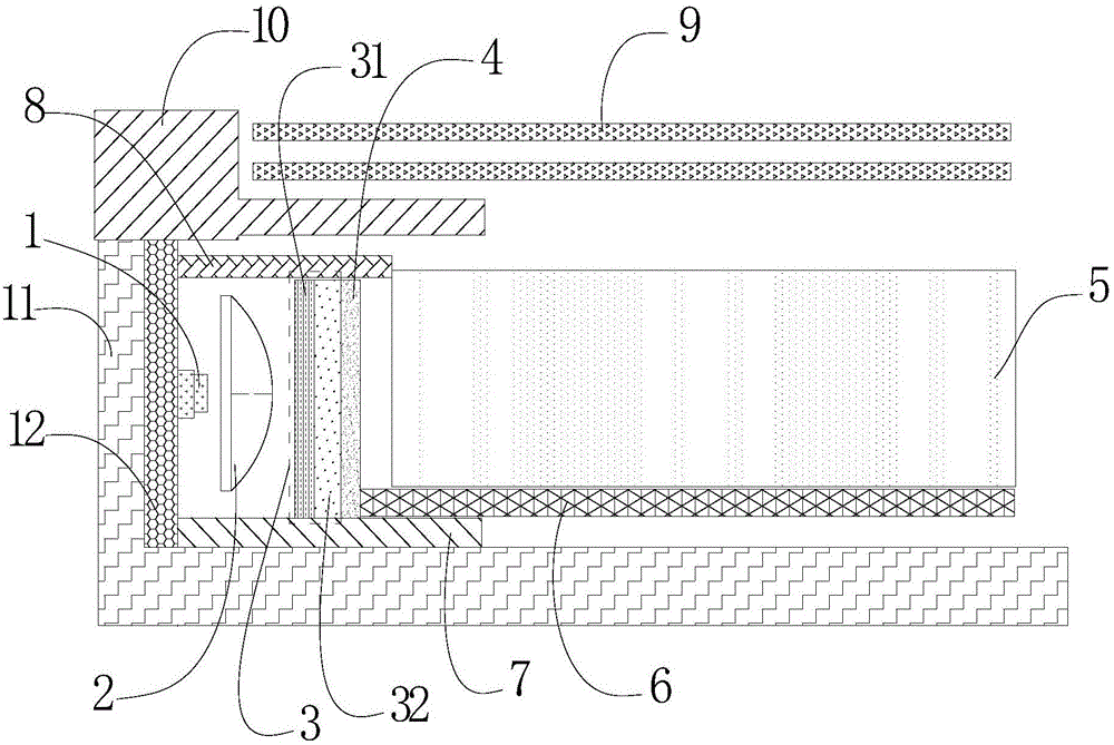
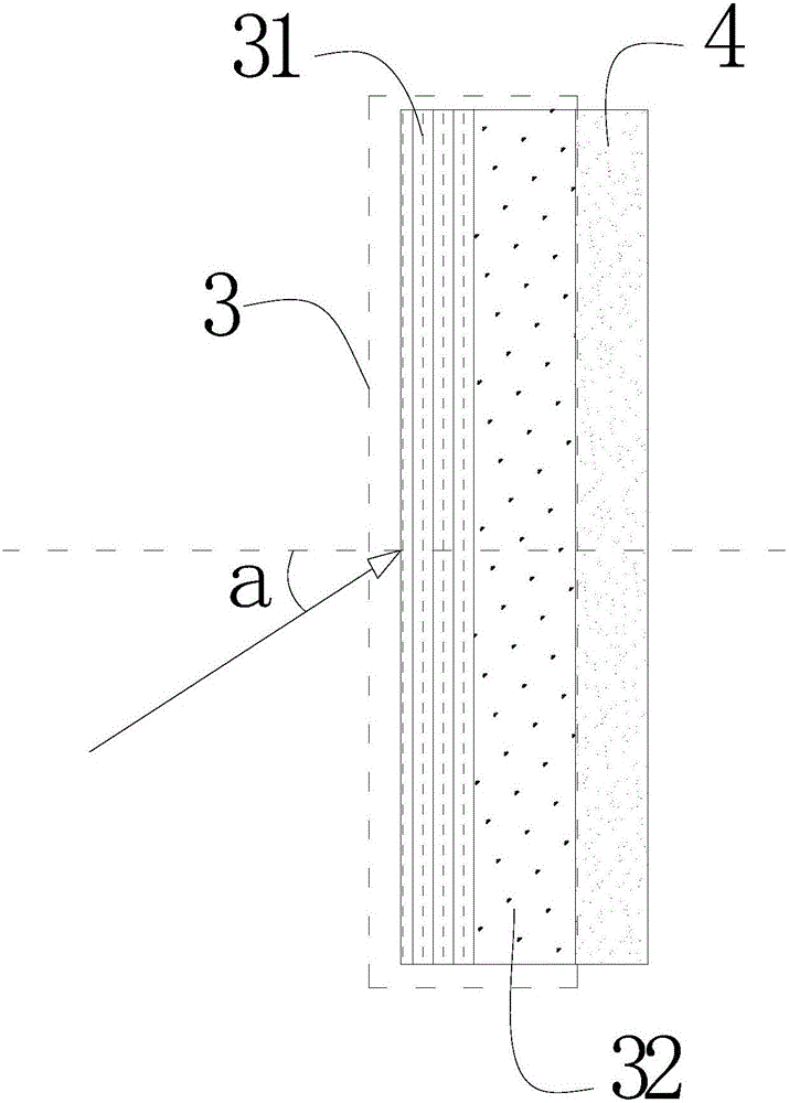
[0029] The principle of the present invention is to adjust the light from the LED light source 1 to light in a preset angle range through the collimator lens 2, so that the incident angle a of the incident light is relatively small, usually less than 30°, and then the light from the multilayer optical film When the filter 3 passes through the multilayer optical film filter 3 , only the light with a narrower wavelength range is allowed to pass through, so only the light with a narrower wavelength range is guided to the liquid crystal display screen by the light guide plate 5 . Among them, the smaller the incident angle a of the light, the better the effect of improving the color gamut.

[0030] Please refer to figure 1 and figure 2 , figure 1 It is a cross-sectional view of a backlight module of this embodiment, figure 2 It is a schematic diagram of the incident angle a formed by the light emitted from the collimating lens 2 and the multilayer optical film filter 3 in this...

Embodiment 2

[0049] A liquid crystal display of the present invention includes a backlight module and a liquid crystal display panel, wherein the backlight module is the backlight module described in Embodiment 1, and the backlight module has been described in detail in Embodiment 1. No further discussion here.

[0050] A kind of liquid crystal display of the present invention, its backlight module is by combining collimating lens 2, multi-layer optical film filter 3 and diffusion layer 4, makes the light of LED light source 1 with less incident light through collimating lens 2 Angle a is incident on the multi-layer optical film filter 3, so that the transmittance of the required light is greatly improved, and the liquid crystal display reaches the same color gamut as the current liquid crystal display with Cd element quantum dots, and can also achieve green without Cd The purpose of the element, the color saturation of the liquid crystal display can be increased to more than 110%, which c...


PUM

PropertyMeasurementUnit
Wavelengthaaaaaaaaaa

Abstract

The invention provides a backlight module and a liquid crystal displayer. The backlight module comprises an LED light source, a collimating lens, a plurality of layers of optical film light filters, a diffusion layer, a light guide plate, reflector plate, an adhesive frame and a back plate, wherein the collimating lens is used for adjusting light emitted by the LED light source to be light within the preset angle range and enabling the light to be emitted out from the surface; the optical film light filters are used for enabling light with the preset wavelength range to pass and filtering out light which is not within the preset wavelength range. The liquid crystal displayer can reach the color gamut equal to that of an existing Cd element quantum dot liquid crystal displayer, and achieve the purpose of being green and free of Cd elements.

Description

【Technical field】 [0001] The invention relates to the field of liquid crystal displays, in particular to a backlight module and a liquid crystal display. 【Background technique】 [0002] Liquid crystal display (Liquid Crystal Display, LCD) and other flat display devices are widely used in mobile phones, televisions, personal digital assistants, digital cameras, notebooks, etc. Various consumer electronic products such as computers and desktop computers have become the mainstream of display devices. Most of the liquid crystal display devices currently on the market are backlight liquid crystal displays, which include a liquid crystal display panel (TFT-LCD) and a backlight module. The working principle of the liquid crystal display panel is to place liquid crystal molecules between two parallel glass substrates. There are many vertical and horizontal small wires between the two glass substrates. The direction of the liquid crystal molecules is controlled by electrifying or no...

Claims


Application Information

Patent Timeline
IPC IPC(8): G02F1/13357
CPCG02F1/133615
Inventor 樊勇
Owner SHENZHEN CHINA STAR OPTOELECTRONICS TECH CO LTD
Learn More