Cutting head with positioning mechanism, cutting device and cutting method

A positioning mechanism and cutting device technology, applied in welding equipment, laser welding equipment, metal processing equipment, etc., can solve the problems of difficult cutting and blanking, and achieve the effect of simple application

Inactive Publication Date: 2016-11-23
WUHAN TIANQI LASER EQUIP MFG
View PDF8 Cites 5 Cited by
  • Summary
  • Abstract
  • Description
  • Claims
  • Application Information

AI Technical Summary

Problems solved by technology

[0003] In view of the defects existing in the prior art, the purpose of the present invention is to provide a cutting head with a positioning mechanism, a cutting device and a cutting method, which realizes the precise cutting of parts and solves the major problem of difficult cutting and blanking

Method used


Image

  • Cutting head with positioning mechanism, cutting device and cutting method
  • Cutting head with positioning mechanism, cutting device and cutting method
  • Cutting head with positioning mechanism, cutting device and cutting method

Examples


Embodiment Construction

[0024] The present invention will be described in further detail below in conjunction with the accompanying drawings and embodiments.

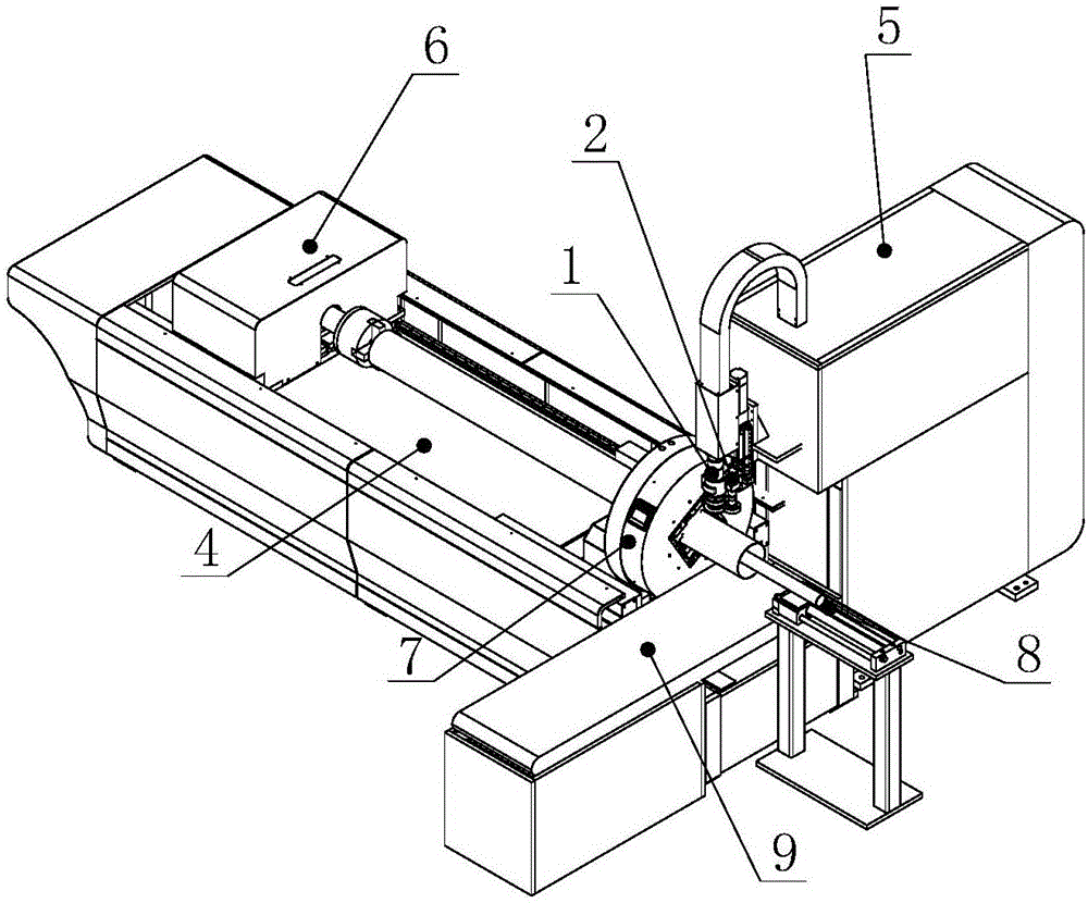
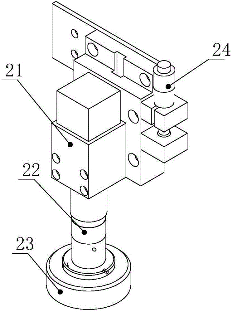
[0025] see figure 1 with figure 2 As shown, the embodiment of the present invention provides a cutting head with a positioning mechanism, the side of the cutting head 1 is provided with a visual imaging unit 2, and the visual imaging unit 2 includes a CCD camera 21 connected in sequence from top to bottom , a depth-of-field lens 22 and a ring light source 23, and the side of the CCD camera 21 is provided with a lifting regulator 24, which is used to adjust the lifting height of the depth-of-view lens 22.

[0026] Specifically, the CCD camera 21 is black and white with 130W pixels and a resolution of 1280*1024. In this embodiment, the 4.130-CCD camera uses a Gigabit Ethernet interface, and it is recommended to use a Gigabit network card or a switch with an intel chip. The overall dimensions are 50mm*38mm*38mm. The CCD adopts a standard C-t...


PUM

PropertyMeasurementUnit
deformity rateaaaaaaaaaa

Abstract

The invention discloses a cutting head with a positioning mechanism, a cutting device and a cutting method and relates to the technical field of laser cutting. A visual imaging unit is arranged at a side part of the cutting head; the visual imaging unit comprises a CCD (Charge Coupled Device) camera, a deep focus camera lens and an annular light source, which are connected in sequence from top to bottom; a lifting adjusting device is arranged at the side part of the CCD camera; and the lifting adjusting device is used for adjusting the lifting height of the deep focus camera lens. With the adoption of the cutting head with the positioning mechanism, the cutting device and the cutting method, accurate cutting of parts is realized and the major problem that cutting blanking is difficult is solved.

Description

technical field [0001] The invention relates to the technical field of laser cutting, and relates to a cutting head with a positioning mechanism, a cutting device and a cutting method. Background technique [0002] At present, there are various mass-produced pipe fittings and flat parts on the market. After the processing is completed, they need to be cut one by one by a laser cutting machine to form standard parts. However, due to the different positions, sizes or shapes of the parts during the batch production process, it is impossible to quickly batch the parts. It leads to low processing efficiency and very difficult processing. Contents of the invention [0003] In view of the defects in the prior art, the purpose of the present invention is to provide a cutting head with a positioning mechanism, a cutting device and a cutting method, which realizes the precise cutting of parts and solves the major problem of difficult cutting and blanking. [0004] In order to achi...

Claims


Application Information

Patent Timeline
Patent Type & Authority Applications(China)
IPC IPC(8): B23K26/38B23K26/08B23K26/70
CPCB23K26/38B23K26/08B23K26/702
Inventor 胡中元李学文
Owner WUHAN TIANQI LASER EQUIP MFG
Why Eureka
Try Eureka