
Laser cutting laser head cooling device

A technology of laser cutting and cooling device, used in laser welding equipment, welding equipment, metal processing equipment, etc. problem, to achieve the effect of high cooling efficiency and speeding up the cooling speed

Inactive Publication Date: 2016-11-23
SUZHOU HUANING MACHINERY MFG
View PDF6 Cites 2 Cited by
  • Summary
  • Abstract
  • Description
  • Claims
  • Application Information

AI Technical Summary

Problems solved by technology

[0003] Due to the high power density carried by the laser, when the laser is irradiated on the reflector and focus lens, even if the reflector and focus lens only absorb a very small part of the energy of the laser, it will still cause the reflector, focus lens and light tube fever
Especially when the laser head works for a long time, it will cause the temperature of the light tube to rise, causing damage to the focusing lens and reflector

Method used


Image

  • Laser cutting laser head cooling device

Examples


Embodiment Construction

[0017] The present invention will be further described below in conjunction with accompanying drawing:

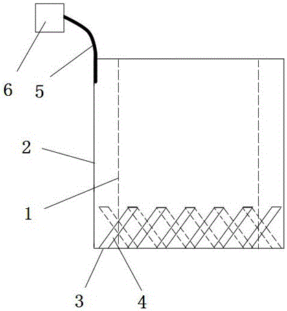
[0018] The laser head cooling device for laser cutting is characterized in that a water injection wall (2) is arranged on the outer wall (1) of the laser head, and the axial cross-section shape of the water injection wall (2) is circular, and the lower end of the water injection wall (2) is connected to the The outer wall (1) of the laser head is connected to form a bottom surface (3), and several water spray pipes (4) inclined upward are arranged on the bottom surface (3), and the water spray pipes (4) spray water at a uniform speed, and the water injection The upper end of the wall (2) is provided with a water-absorbing connecting line (5), and the water-absorbing connecting line (5) is connected to the water-absorbing material (6).

[0019] Further, the water-absorbing material (6) is a sponge.

[0020] Further, the thickness of the water injection wall (2) is 1 mm.

...


PUM

PropertyMeasurementUnit
thicknessaaaaaaaaaa
diameteraaaaaaaaaa

Abstract

The invention provides a laser cutting laser head cooling device with high efficiency. The laser cutting laser head cooling device is characterized in that a water injecting wall 2 is arranged on a laser head outer wall 1; the shaft section of the water injecting wall 2 is circular; the lower end of the water injecting wall 2 is connected with the laser head outer wall 1 to form a bottom surface 3; multiple water spraying pipes 4 are upwards inclined on the bottom surface 3; the water spraying pipes 4 spray water at a constant speed; and a water sucking connection line 5 is arranged at the upper end of the water injecting wall 2, and is connected with a water sucking material 6. The water spraying pipes spray the water at the constant speed, so that the flowing water is contacted with the laser head outer wall for cooling; when the laser head is overheated, the water is quickly evaporated, so that the heat is sucked for cooling; when the water evaporation speed is slower, the redundant water is absorbed by the water sucking material through the water sucking connection line to realize automatic heat dissipation; and the flowing water accelerates the cooling speed, so that the cooling efficiency is high.

Description

technical field [0001] The invention relates to the field of laser cutting, in particular to a cooling device for a laser head for laser cutting. Background technique [0002] Laser cutting is to focus the laser emitted from the laser into a high power density laser beam through the optical path system. The laser beam irradiates the surface of the workpiece to make the workpiece reach the melting point or boiling point, and at the same time, the high-pressure gas coaxial with the beam blows away the molten or vaporized metal. With the movement of the relative position of the beam and the workpiece, the material will eventually form a slit, so as to achieve the purpose of cutting. [0003] Due to the high power density carried by the laser, when the laser is irradiated on the reflector and focus lens, even if the reflector and focus lens only absorb a very small part of the energy of the laser, it will still cause the reflector, focus lens and light tube fever. Especially ...

Claims


Application Information

Patent Timeline
Patent Type & Authority Applications(China)
IPC IPC(8): B23K26/70B23K26/38
CPCB23K26/703B23K26/38
Inventor 钱海萍
Owner SUZHOU HUANING MACHINERY MFG
Learn More