Welding die locking device

A locking device, welding mold technology, applied in auxiliary devices, welding equipment, auxiliary welding equipment and other directions, can solve the problems of insufficient flexibility, weak mold locking, weak welding, etc., to improve flexibility and versatility , Improve the efficiency of mold clamping and avoid the effect of manual positioning and clamping

Active Publication Date: 2016-11-23
金焊机械(太仓)有限公司
View PDF7 Cites 2 Cited by
  • Summary
  • Abstract
  • Description
  • Claims
  • Application Information

AI Technical Summary

Problems solved by technology

[0003] At present, most of the traditional welding mold locking devices use quick-change fixtures; through the expansion and contraction of the cylinder, the locking and loosening of the mold is driven to achieve the purpose of quick replacement; however, traditional molds usually exist, and the mold locking is not easy. Firmness, shaking and other phenomena; in the process of mold transfer, it is easy to cause deviations in welding positioning, and phenomena such as weak welding, missing welding, and less welding occur, which greatly affects the processing quality of products, resulting in increased scrap rate and waste of cost , affecting the corporate image
[0004] In addition, in order to meet the requirements of welding precision in traditional welding molds, the structure of the locking device is usually more complex and the manufacturing cost is higher; at the same time, the traditional locking devices are mostly non-standard parts, which have poor versatility and insufficient flexibility ;After the product is replaced, it causes idleness and waste of the locking device

Method used


Image

  • Welding die locking device
  • Welding die locking device
  • Welding die locking device

Examples


Embodiment

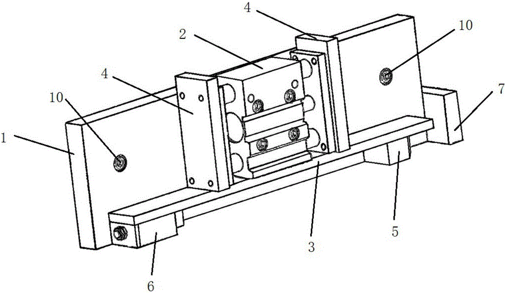
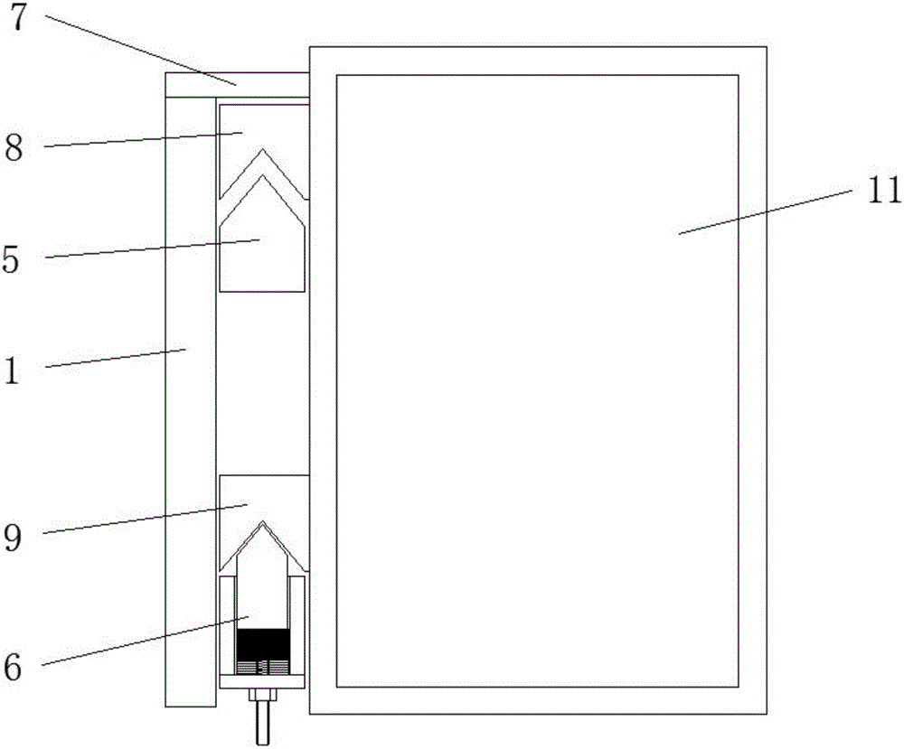
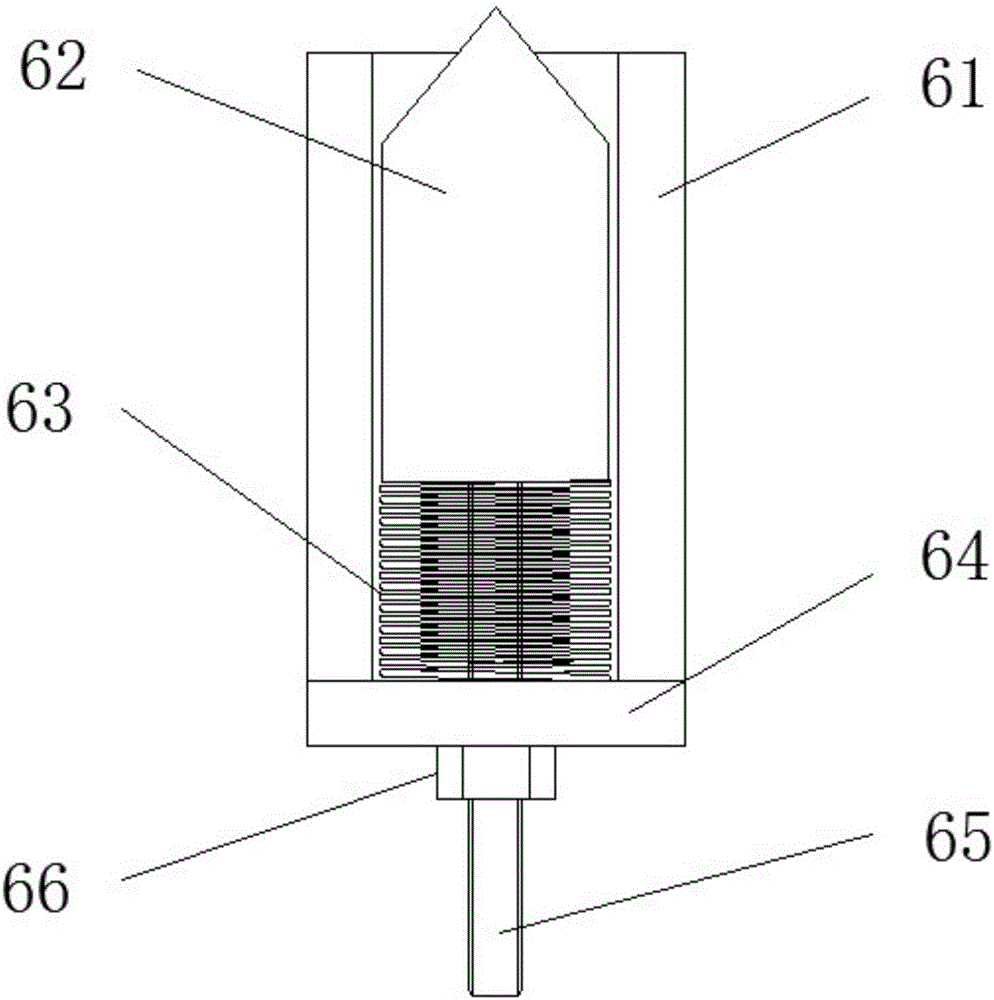
[0021] A welding mold locking device according to the present invention, such as figure 1 As shown, it includes: a support plate 1 installed on the machine tool sliding frame, a locking cylinder 2 fixed on the support plate 1, and a lock head fixing plate 3; The piston rod of the cylinder 2 is fixedly connected; the bottom of the lock head fixing plate 3 is provided with a front lock head 5 and a rear lock head module 6 arranged side by side, such as figure 2 As shown, the welding mold locking device of the present invention also includes a front block 8 matched with the front lock head 5 and a rear block 9 matched with the rear lock head module 6 arranged in parallel on the welding mold frame 11; like image 3 As shown, the rear lock module 6 includes: a lock block 61, a sliding lock 62, a spring 63 and a fixing plate 64; Figure 4 As shown, the inside of the lock block 61 is provided with a through chute 611; the sliding lock 62 is slidably arranged in the chute 611; the ...


PUM


Abstract

The invention discloses a welding die locking device, and belongs to the field of die clamping. The welding die locking device comprises a supporting plate mounted on a machine tool slippage frame, and a locking cylinder and a tapered end fixing plate which are fixedly arranged on the supporting plate, wherein the tapered end fixing plate is fixedly connected with a piston rod of the locking cylinder through connection plates; a front tapered end and a rear tapered end module which are arrayed side by side in tandem are arranged at the bottom of the tapered end fixing plate; the rear tapered end module comprises a tapered end clamping block, a sliding tapered end, a spring and a fixed plate; a through sliding slot is formed in the tapered end clamping block; the sliding tapered end is arranged in the sliding slot in a sliding manner; the fixed plate is fixedly arranged at one end of the sliding slot; the spring is arranged between the sliding tapered end and the fixed plate. The spring is matched with the sliding tapered end, so that the welding die locking device can freely expand and retract front and back according to an actual distance so as to guarantee that the front tapered end is fully clamped and to improve the flexibility and the generality of equipment, and the application range is wide; and furthermore, the welding die locking device has the characteristics of being capable of adjusting the tightness of the spring, convenient to mount, simple in structure, low in purchase cost and the like.

Description

technical field [0001] The invention relates to the technical field of mold clamping, in particular to a welding mold locking device. Background technique [0002] In the field of mold manufacturing and processing, the mold is a tool used for forming. The manufacturer designs a matching mold according to the customer's requirements for product appearance or function, so as to achieve the purpose of rapid and unified production. In the welding process of hardware products, robot welding technology is usually used to achieve fast and high-precision welding. Therefore, in order to improve the welding production efficiency, multiple tooling molds are used to assemble and weld in turn to meet the welding needs; to ensure the working efficiency of the equipment, improve production and increase costs. [0003] At present, most of the traditional welding mold locking devices use quick-change fixtures; through the expansion and contraction of the cylinder, the locking and loosening ...

Claims


Application Information

Patent Timeline
Patent Type & Authority Applications(China)
IPC IPC(8): B23K37/04
CPCB23K37/0435
Inventor 周春伯周钰祥
Owner 金焊机械(太仓)有限公司
Why Eureka
Try Eureka