

Hydraulic tire vulcanizing machine
A vulcanizing machine and hydraulic technology, which is applied in the field of rubber machinery, can solve the problems of small installation and maintenance space, large area occupied by vulcanizing machines, and large volume of afterburner cylinders, and achieve convenient maintenance, increase equipment installation and maintenance space, The effect of increasing the maintenance space
- Summary
- Abstract
- Description
- Claims
- Application Information
AI Technical Summary
Problems solved by technology
Method used
Image

Examples
Embodiment 1
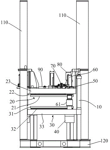
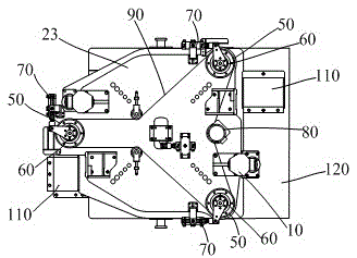
[0029] refer to picture 1 to picture 3. The hydraulic vulcanizing machine of this embodiment includes a vulcanization chamber, a mold opening and closing cylinder 10, a base 120 and a plurality of guide posts 110 fixed on the base 120, and the vulcanization chamber includes an upper vulcanization chamber 20 and a lower vulcanization chamber 30 , the upper vulcanization chamber 20 includes an upper hot plate 21, an upper heat shield 22 and an upper main board 23, and the lower vulcanization chamber 30 includes a lower hot plate 31, a lower heat insulating board 32 and a lower main board 33, and the vulcanization chamber is provided with clamping, It is a multiple integrated mechanism that integrates the functions of afterburner and mold adjustment.
[0030] In order to improve the centering accuracy of the upper hot plate 21 and the lower hot plate 31 during mold closing, and further improve the vulcanization quality, in this embodiment, the lower vulcanization chamber 30 is...
Embodiment 2
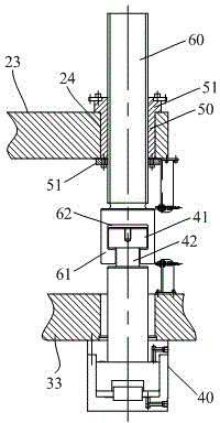
[0040] refer to picture 7. Each of the integrated mechanisms in this embodiment also includes an afterburning cylinder 40, a nut 50 and a screw 60 that cooperates with the nut 50. The difference from the first embodiment is that the cylinder of the afterburning cylinder 40 in this embodiment The body is fixed on the upper main board 23, and the lower main board 33 is provided with a screw nut installation hole 34 and a driving part 70; the screw nut 50 is rotatably installed on the lower main board 33 in the screw nut installation hole 34, and the screw nut 50 has The limit part 51 that restricts its movement up and down relative to the lower main board 33, that is, the screw nut 50 can only rotate relative to the lower main board 33, but cannot move up and down; similarly, different from Embodiment 1, it is used to drive multiple integrated components in this embodiment. The screw nut 50 of the mechanism is arranged on the lower main board 33 on the driving part 80 and the t...
Embodiment 3
[0044] refer to picture 8. The difference from Embodiment 1 and Embodiment 2 is that each integrated mechanism in this embodiment includes an afterburner cylinder 40, a clamping rod 100, a screw nut 50 and a screw rod 60 that cooperates with the screw nut 50, and the clamping rod 100 Vertically fixed on the upper main board 23, the lower main board 33 is provided with a screw nut mounting hole 34, and the screw nut 50 is rotatably installed on the lower main board 33 in the screw nut mounting hole 34, and the screw nut 50 has a function to limit its relative lower position. Main board 33 moves up and down the limit portion 51, afterburner oil cylinder 40 is positioned between clamping rod 400 and screw mandrel 60, and its cylinder body is connected to the upper end of screw mandrel 60; The driving screw 60 is driven to rotate in the state of adding force, and then the driving cylinder 40 is driven to rotate so that the upper end of the cylinder rod is connected with the lower...
PUM
 Abstract
Description
Claims
Application Information