
Energy absorption type bumper

A bumper, together technology, applied in the direction of bumper, vehicle safety arrangement, transportation and packaging, etc., can solve the problems of reducing the collision force to a minimum, limited installation space of parts, and low impact resistance of bumpers, etc., to achieve Easy to use and promote, guarantee personal and property safety, compact installation and reasonable effect

Inactive Publication Date: 2016-11-23
GUIZHOU UNIV
View PDF6 Cites 3 Cited by
  • Summary
  • Abstract
  • Description
  • Claims
  • Application Information

AI Technical Summary

Problems solved by technology

Most of the existing automobile bumpers adopt a rigid connection method, which is easy to be damaged when a collision occurs, and the impact resistance of the bumper is also relatively low, so it is difficult to reduce the collision force to a minimum; The bumper can absorb part of the impact energy, but most of it is still transmitted to the body, and these bumpers are difficult to avoid secondary collisions during emergency parking, resulting in damage to the body and casualties
[0003] Existing bumper generally adopts to strengthen the rigidity of oneself in addition to avoid the problem that is easy to be damaged when colliding, and what have even is also provided with reinforcing rib on the cylinder body to improve the rigidity of cylinder body, although this bumper can be to a certain extent The upper protection body is not easy to be damaged, but it brings greater damage to the external collision body
Although some bumpers have better collision performance, they take up a lot of space on the car, so the installation space of other auto parts is severely limited.
[0004] Therefore, the current automobile bumper still has many limitations.

Method used


Image

  • Energy absorption type bumper

Examples


Embodiment Construction

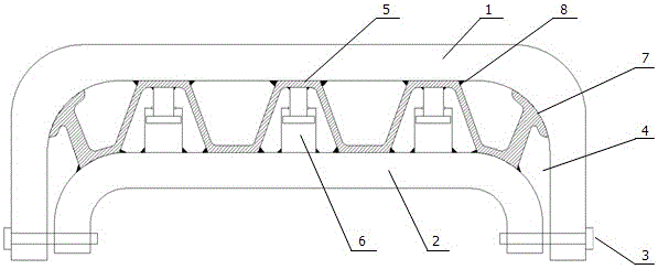
[0017] Such as figure 1 It is a structural schematic diagram of the present invention, an energy-absorbing bumper, which includes a bumper front "∩" beam 1 and a rear "∩" beam 2 fixedly connected together by bolts 3, and the front "∩" beam of the bumper A buffer chamber 4 is formed between 1 and the rear "∩" beam 2, and a folding support plate 5 is arranged in the buffer chamber 4. The folding support plate 5 is connected with the front "∩" beam 1 and the rear "∩" beam 2 of the bumper through a welding block 8 . The air spring 6 is installed in the lower groove of the foldable support plate 5, and the upper and lower ends of the air spring 6 are connected with the upper end of the foldable support plate 5 and the bumper rear “∩” beam 2 by a welding block 8.

[0018] The two rounded corners at the end of the folding support plate 5 are circular arc “T” support structures 7 . The number of foldable support plates 5 is more than three.

[0019] The inner side of the folding su...


PUM


Abstract

The invention relates to the technical field of passive safety of vehicles, in particular to an energy absorption type bumper. A front inverted-U-shaped beam and a rear inverted-U-shaped beam of the bumper are fixedly connected together through a bolt, a buffer chamber is formed between the front inverted-U-shaped beam and the rear inverted-U-shaped beam, a folding supporting plate and at least 5 air springs are installed in the buffer chamber, and two round corners at the tail end of the folding supporting plate are of circular-arc T-shaped supporting structures, so that a buffering effect is played when collision occurs at the round corners. The bumper is simple in structure and compact and reasonable in installation, does not need a too large space, can effectively decrease and absorb most of outside impact energy and better plays buffering and vibration attenuation effects, the impact resistance of the vehicle bumper is improved, meanwhile the collision strength can be minimized, accordingly the personal and property safety can be effectively ensured, and the safety of an automobile in running is greatly improved. Therefore, the energy absorption type bumper is easy to use and popularize.

Description

technical field [0001] The invention relates to the technical field of automobile passive safety, in particular to an energy-absorbing bumper. Background technique [0002] The bumper belongs to the safety auxiliary device of the car. It is installed at the front and rear ends of the car. It can alleviate the external impact force and protect the body in the event of a collision, preventing the body from being damaged by direct impact. Most of the existing automobile bumpers adopt a rigid connection method, which is easy to be damaged when a collision occurs, and the impact resistance of the bumper is also relatively low, so it is difficult to reduce the collision force to a minimum; The bumper can absorb part of the impact energy, but most of it is still transmitted to the body, and it is difficult for these bumpers to avoid secondary collisions during emergency parking, resulting in damage to the body and casualties. [0003] Existing bumper generally adopts to strengthen...

Claims


Application Information

Patent Timeline
Patent Type & Authority Applications(China)
IPC IPC(8): B60R19/18
CPCB60R19/18B60R2019/1806B60R2019/186
Inventor 贺迪华罗卫东黄琳森
Owner GUIZHOU UNIV
Learn More