Chain adjuster assembly and motorcycle thereof

A regulator and chain technology, used in vehicle parts, vehicle gearboxes, chain/belt drives, etc., can solve the problems of unreliable limit, affect limit accuracy, poor versatility, etc., and reduce mold costs and materials. High cost and good versatility

Active Publication Date: 2016-11-23
CHONGQING LONCIN MOTOR
View PDF4 Cites 2 Cited by
  • Summary
  • Abstract
  • Description
  • Claims
  • Application Information

AI Technical Summary

Problems solved by technology

[0002] The motorcycle chain adjuster assembly body is installed on the left and right ends of the rear wheel shaft, and is located in the left and right tubes of the flat fork. The side tubes of the flat fork are provided with strip holes for the rear wheel shaft to pass through. The chain adjuster assembly The stud on the body passes through the baffle at the rear end of the flat fork side tube and is locked by a nut. When the nut is turned, the stud drives the main body of the chain adjuster assembly to move back and forth in the flat fork side tube, and then drives the rear axle Move synchronously along the bar-shaped hole on the side tube of the flat fork to realize the adjustment of the chain tension. In order to visually display the relative position of the wheel shaft and the bar-shaped hole, it is convenient to move the two ends of the wheel shaft along the bar-shaped hole of the chain adjuster assembly To keep the amount consist

Method used


Image

  • Chain adjuster assembly and motorcycle thereof
  • Chain adjuster assembly and motorcycle thereof
  • Chain adjuster assembly and motorcycle thereof

Examples


Embodiment Construction

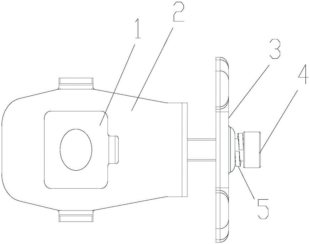
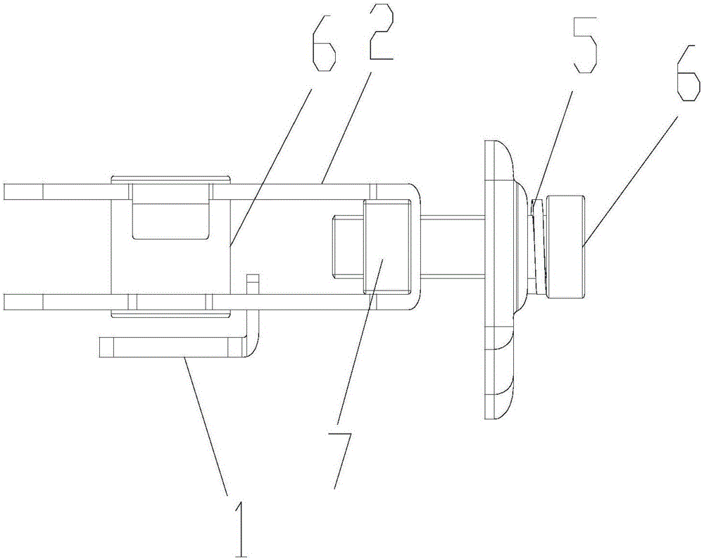
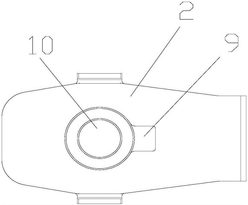
[0025] figure 1 It is a schematic diagram of the structure of the present invention; as shown in the figure: the chain adjuster assembly of this embodiment includes a flat fork and a chain adjustment assembly installed in the side tube 11 of the flat fork. Adjuster main body 2 with hole 10 and sliding fit with the side tube 11 of the flat fork, a position adjustment mechanism for driving the adjuster main body 2 to move longitudinally along the side tube 11, and the adjuster hanging plate 1 for indicating the position of the axle, the adjuster The hanging plate 1 is provided with a limit lug 8, and the lateral sides of the limit lug 8 cooperate with the regulator main body 2 to limit its rotation around the axis of the axle through hole 10. The bending surface of the existing hanging plate 1 is along a flat surface. The vertical setting of the fork and the contact of the flat fork are used to limit the position. The angle error of the bending will affect the accuracy of the li...


PUM


Abstract

The invention discloses a chain adjuster assembly. The chain adjuster assembly comprises a bottom fork and a chain adjusting component mounted in a bottom fork side pipe. The chain adjusting component comprises an adjuster main body which is provided with a wheel axle via hole and is in sliding fit with the bottom fork side pipe, a position adjusting mechanism used for driving the adjuster main body to slide longitudinally along the bottom fork side pipe, and an adjuster suspension plate used for indicating the position of a wheel axle. The adjuster suspension plate is provided with a limiting lug, and the two transverse side faces of the limiting lug are used for being matched with the adjuster main body so that the limiting lug can limit rotation of the adjuster main body around the wheel axle via hole. Accordingly, the error of the bending angle of the limiting lug does not affect the limiting precision of the limiting lug, the universality of the assembly is good, and the assembly can be used for sectional material bottom forks and can also be used for special-shaped bottom forks. In addition, the suspension plate in the structural form can be exchanged left and right, and the mold cost is reduced.

Description

technical field [0001] The invention relates to a chain adjuster component, in particular to a chain adjuster assembly and a motorcycle thereof. Background technique [0002] The motorcycle chain adjuster is installed on the left and right ends of the rear axle as a whole, and is located in the left and right pipes of the flat fork. The side pipe of the flat fork is provided with a strip hole for the rear axle to pass through. The stud on the body passes through the baffle at the rear end of the flat fork side tube and is locked by the nut. When the nut is turned, the stud drives the main body of the chain adjuster assembly to move back and forth in the flat fork side pipe, thereby driving the rear axle. It moves synchronously along the strip hole on the side tube of the flat fork to adjust the tension of the chain. In order to visually display the relative position of the axle and the strip hole, it is convenient for both ends of the axle to move along the strip hole of the...

Claims


Application Information

Patent Timeline
IPC IPC(8): B62M9/16
CPCB62M9/16
Inventor 隆文赟曾昭勇朱大州刘东东李柱庆侯成东
Owner CHONGQING LONCIN MOTOR
Why Eureka
Try Eureka