Case-mold-type capacitor and method for producing same

a capacitor and case-mold technology, applied in the field of case-mold-type capacitors, can solve the problems of difficult to unify the distances between adjacent bus bars in plural case-mold-type capacitors, difficult to dispose of bus bars, etc., and achieve the effects of improving dimensional accuracy, high reliability, and increasing material cos

Active Publication Date: 2015-12-03
PANASONIC INTELLECTUAL PROPERTY MANAGEMENT CO LTD
View PDF8 Cites 6 Cited by
  • Summary
  • Abstract
  • Description
  • Claims
  • Application Information

AI Technical Summary

Benefits of technology

[0014]The case-mold-type capacitor improves dimensional accuracy between terminal portions of the first and second bus bars without increasing material cost, and has high reliability.

Problems solved by technology

However, it is difficult to dispose bus bars 102, 103, 104, and 105 to the same positions without error, and it is difficult to unify all the distances between adjacent bus bars in plural case-mold-type capacitors 101.

Method used


Image

  • Case-mold-type capacitor and method for producing same
  • Case-mold-type capacitor and method for producing same
  • Case-mold-type capacitor and method for producing same

Examples


exemplary embodiment 1

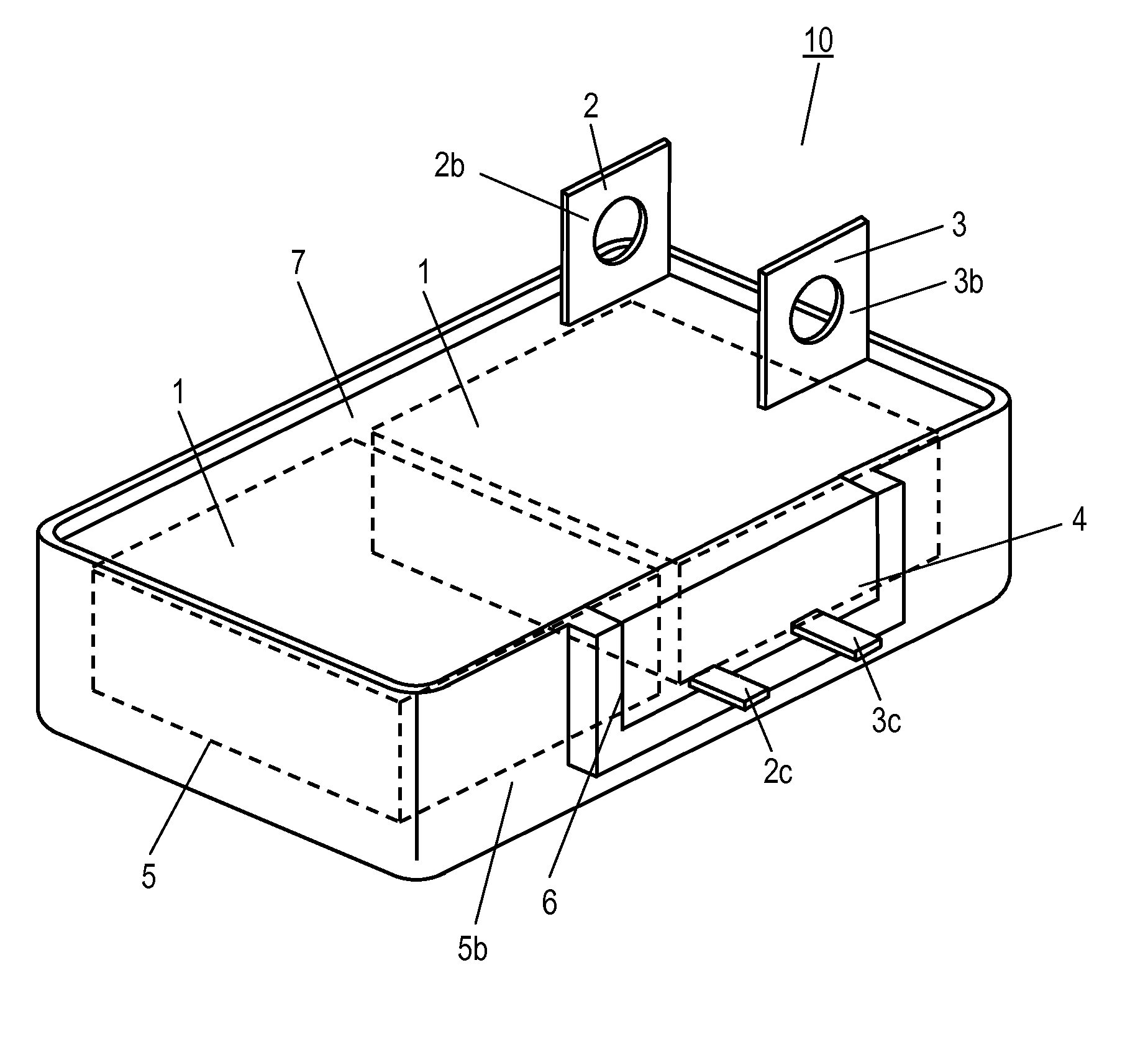
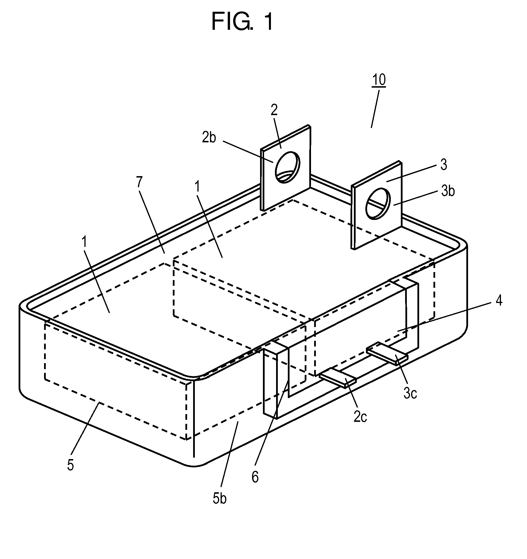
[0037]FIG. 1 is a perspective view of case-mold-type capacitor 10 in accordance with Exemplary Embodiment 1 of the present invention. Case-mold-type capacitor 10 includes case 5, capacitor element 1 housed in case 5, mold resin 7 filled into case 5 so as to cover capacitor element 1, and bus bars 2 and 3 electrically connected to capacitor element 1. Bus bar 2 includes terminal portions 2b and 2c exposed to the outside of case 5. Bus bar 3 includes terminal portions 3b and 3c exposed to case 5.

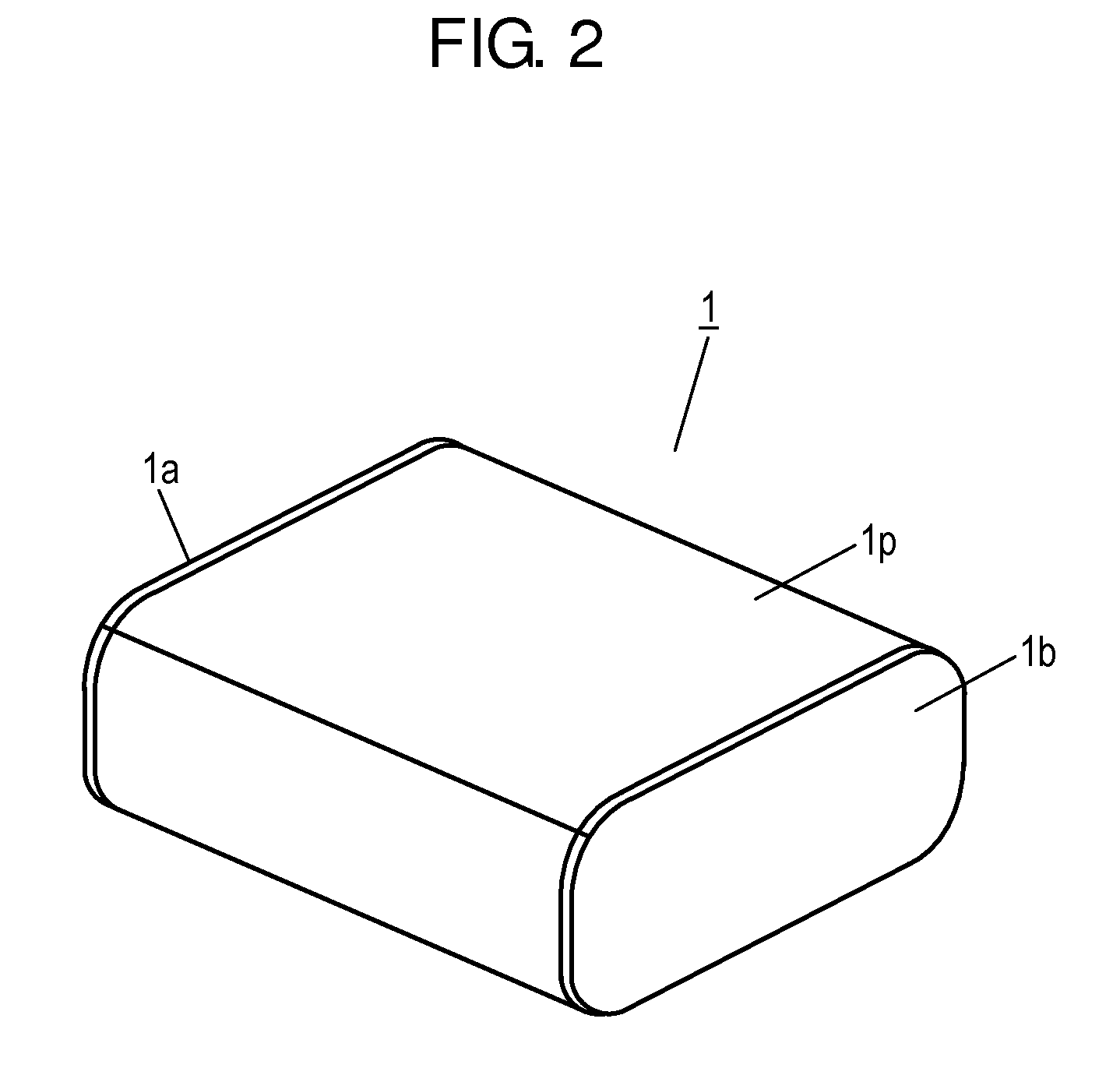
[0038]FIG. 2 is a perspective view of capacitor element 1. Capacitor element 1 includes capacitor element body 1p and electrodes 1a and 1b provided on capacitor element body 1p. Capacitor element 1 in accordance with Embodiment 1 is a metallized film capacitor element, and is formed by pressing a pair of wound metallized films into a flat shape from upper and lower sides thereof. The metallized films include a dielectric film made of, for example, polypropylene, and a metal vapor-deposition el...

exemplary embodiment 2

[0068]FIG. 7 is a perspective view of case-mold-type capacitor 20 in accordance with Exemplary Embodiment 2 of the present invention. In FIG. 7, the components identical to those of case-mold-type capacitor 10 in accordance with Embodiment 1 shown in FIGS. 1 to 6 are denoted by the same reference numerals. Case-mold-type capacitor 20 in accordance with Embodiment 2 includes case 25 and sealing plate 24 instead of case 5 and sealing plate 4 of case-mold-type capacitor 10 in accordance with Embodiment 1 shown in FIGS. 1 to 6. FIG. 8 is a perspective view of case-mold-type capacitor 20 before being filled with mold resin 7.

[0069]As shown in FIGS. 7 and 8, case 25 and sealing plate 24 of case-mold-type capacitor 20 in accordance with Embodiment 2 have substantially the same shapes as case 5 and sealing plate 4 of case-mold-type capacitor 10 in accordance with Embodiment 1 shown in FIGS. 1 and 6. Sealing plate 24 is joined to case 25 such that sealing plate 24 becomes a part of side wall...


PUM

PropertyMeasurementUnit
voltageaaaaaaaaaa
shapeaaaaaaaaaa
life-timeaaaaaaaaaa

Abstract

A case-mold-type capacitor includes a capacitor element, first and second bus bars connected to the first and second electrodes of the capacitor element, a case accommodating the capacitor element and the first and second bus bars, and a mold resin filling the case therein. The case has a cutaway portion provided therein. A sealing plate joined to the case so as to seal the cutaway portion. The first and second bus bars pass through the sealing plate and are fixed to the sealing plate. The case-mold-type capacitor improves dimensional accuracy between terminal portions of the first and second bus bars without increasing material cost, and has high reliability.

Description

TECHNICAL FIELD[0001]The present invention relates to a case-mold-type capacitor used in various electronic devices, electrical devices, industrial devices, automobiles, and the like, and, in particular, suitable for smoothing and for a filter and a snubber in an inverter circuit for driving a motor of a hybrid automobile, and to a method for manufacturing the capacitor.BACKGROUND ART[0002]In recent years, from the viewpoint of environmental protection, any electrical devices have been controlled by an inverter circuit for promoting energy saving and achieving high efficiency. Particularly, in the automobile industry, technologies, which are eco-friendly and relate to energy saving and high efficiency, have been developed actively. For example, a hybrid electric vehicle (hereinafter, referred to as “HEV”), which runs on an electric motor and an engine, has been introduced into the market.[0003]Since a range of working voltage of electric motors used in HEVs is as high as several hun...

Claims


Application Information

Patent Timeline
Patent Type & Authority Applications(United States)
IPC IPC(8): H01G4/236H01G4/005H01G4/224H01G4/06
CPCH01G4/236H01G4/06Y10T29/51H01G4/224H01G4/005H01G2/04H01G2/10H01G4/228H01G13/003H01G13/006H01G2/103Y02T10/70
Inventor SATO, SHINYAMIURA, TOSHIHISA
Owner PANASONIC INTELLECTUAL PROPERTY MANAGEMENT CO LTD
Why Eureka
Try Eureka