Vertical shaft construction device and using method thereof

A construction device and shaft technology, which is used in shaft equipment, well sinking, earthwork drilling, etc., can solve the problems of vibration damage of newly poured concrete, increase in supporting materials and supporting costs, poor blasting molding, etc., so as to reduce the overhang of the formwork. The effect of hoisting wire ropes and suspending and stabilizing vehicles, supporting materials and supporting costs, noise and dust control

Pending Publication Date: 2018-09-14
CHINA COAL NO 5 CONSTR +1
View PDF0 Cites 7 Cited by
  • Summary
  • Abstract
  • Description
  • Claims
  • Application Information

AI Technical Summary

Problems solved by technology

[0005] 1. Manual excavation or small excavators are used for the surface soil section, manual drilling and blasting are used for the bedrock section, and rock grabbers or small excavators are used for slag removal. The labor intensity of workers is high and the degree of mechanization is low;
[0006] 2. Cannot make full use of the working surface space for parallel construction, and the construction time of each cycle is longer;
[0007] 3. The blasting position of the working face is close to the recently poured concrete, which will cause certain vibration damage to the newly poured concrete;
[0008] 4. The blasting construction has great damage to the surrounding rock of the well wall, and the blasting formation is poor, resulting in difficult support and increased support materials and support costs
[0009] 5. The underground noise and dust in the rock drilling and slag extraction process are large, and the working environment is poor

Method used


Image

  • Vertical shaft construction device and using method thereof
  • Vertical shaft construction device and using method thereof
  • Vertical shaft construction device and using method thereof

Examples


Embodiment

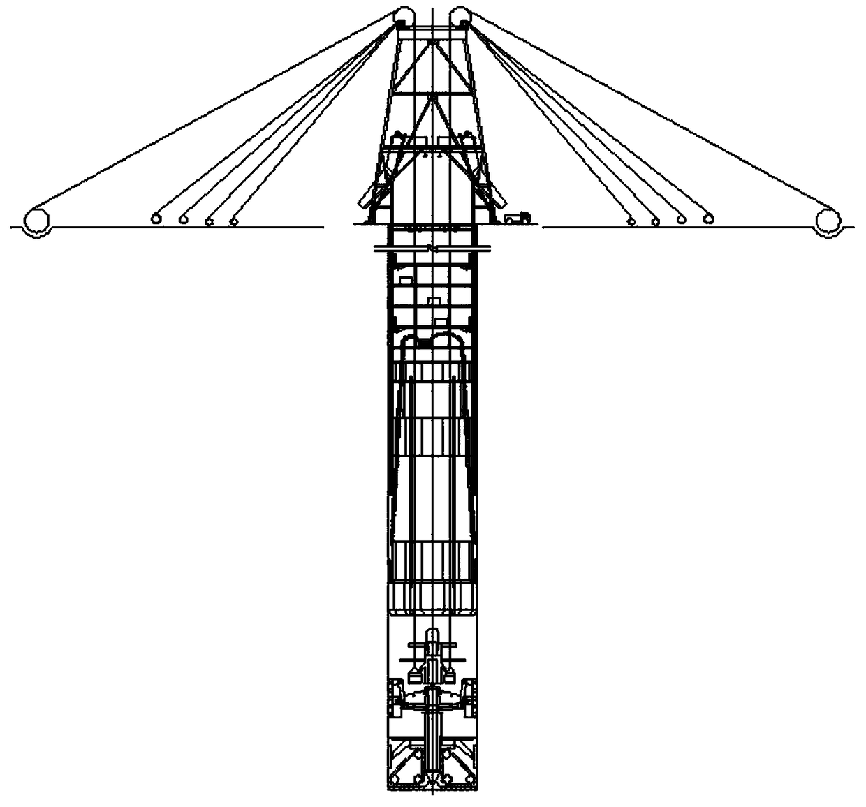
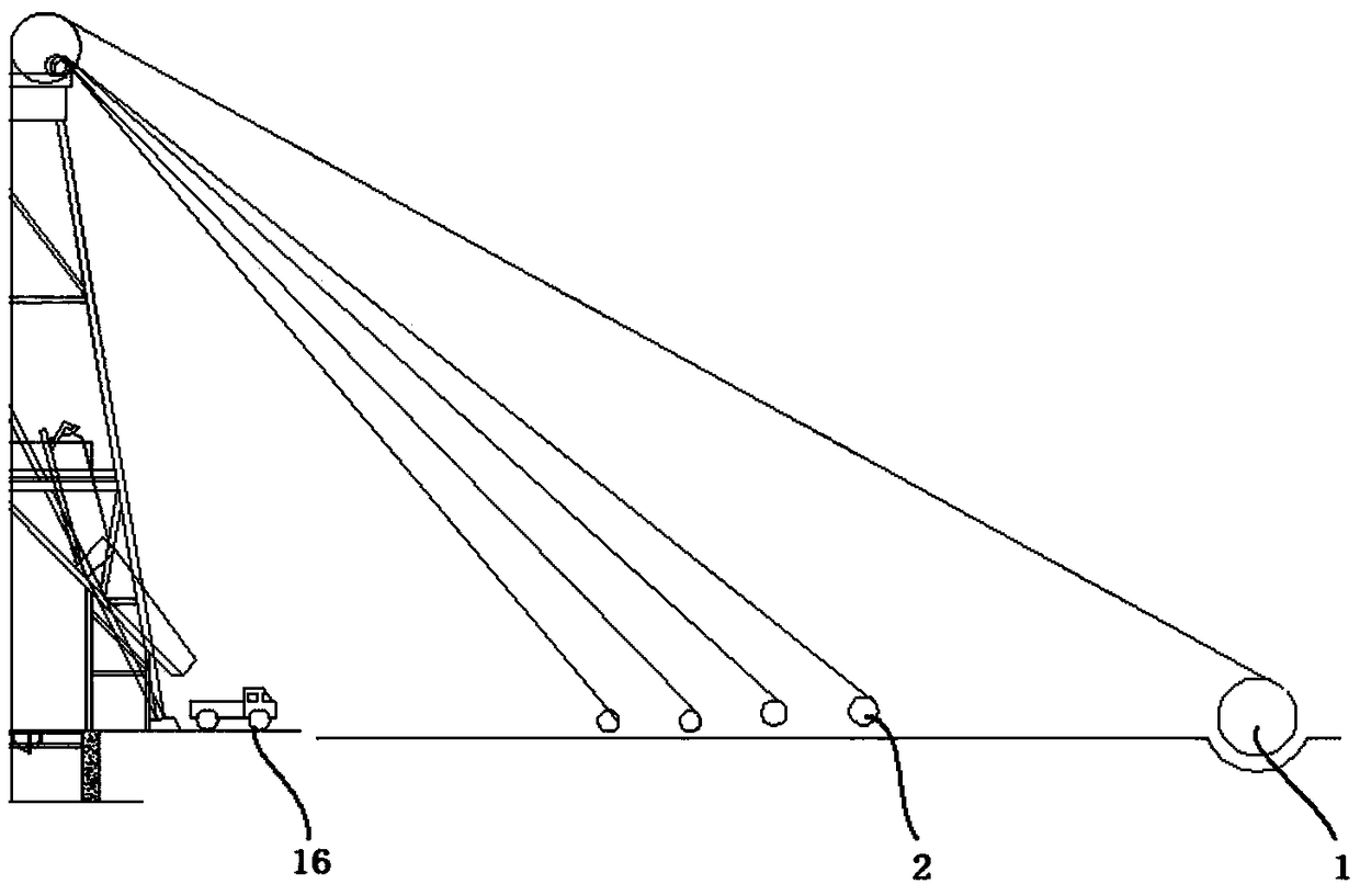
[0047] figure 1 It is an overall structure diagram of the present invention.

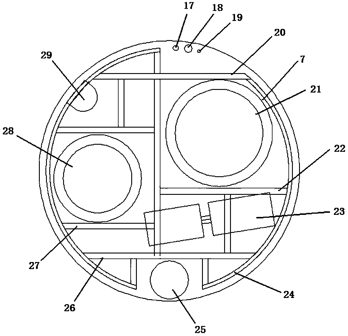
[0048] Such as image 3 , Figure 4 , Figure 5 As shown, a vertical shaft construction device includes a hoist 1, a sinking winch 2, a sinking derrick 3, a sky wheel platform 4, a gangue turning platform 5, a sealing plate 6, and a hanging plate 7. The hanging plate 7 is provided with a supply Electric equipment 11, hydraulic control equipment 12, drainage equipment 13, ash separator 14, and ash separator 14 is provided with ash conveying pipe 15. Such as Figure 6As shown, the bottom of the suspension plate 7 is provided with a non-suspension stepping type seamless formwork 8; the non-suspension stepping type seamless formwork 8 includes an upper support shoe 81, a straight formwork 1 83, a straight formwork 2 84, and a lower support shoe 86, The upper support shoe 81 and the straight formwork one 83 are connected through the stepping oil cylinder 82, the upper support shoe 81 is connected wi...


PUM


Abstract

The invention discloses a vertical shaft construction device which comprises a hoist, shaft sinking winches, a shaft sinking headframe, a head sheave platform, gangue turning platforms, an opening sealing disc and a hanging scaffold. Power supply and distribution equipment, hydraulic control equipment, water drainage equipment and an ash splitter are arranged on the hanging scaffold, and ash slipping pipes are arranged on the ash splitter. Suspension-free stepping-type seamless formworks are arranged below the hanging scaffold and each comprise an upper supporting shoe, a first straight formwork body, a second straight formwork body and a lower supporting shoe; the upper supporting shoes and the first straight formwork bodies are connected through stepping oil cylinders; the upper supporting shoes is connected with the lower supporting shoes through steel wire ropes; and edge feet are arranged between the second straight formwork bodies and the lower supporting shoes. A vertical shafttunneling machine is arranged below the suspension-free stepping-type seamless formworks. The full-section vertical shaft tunneling machine is adopted for tunneling and slag discharge, complete mechanization is achieved, the suspension-free stepping-type seamless formworks are adopted to achieve tunneling and building parallel operation of the vertical shaft, the number of construction labor hoursis reduced, and the construction efficiency is improved.

Description

technical field [0001] The invention relates to the field of shaft shaft construction, in particular to a shaft construction device and a method for using the same. Background technique [0002] At present, in the shaft construction of various shafts, the excavation and masonry construction of the surface soil section mostly adopts the mixed operation method of short-section excavation and masonry of the vertical shaft with comprehensive mechanization. The formwork is used to build the wall, and the bottom unloading bucket is used to feed the concrete. The hanging pan is installed with a fixed centralized ash separator for partitioned and symmetrical pouring. Under normal circumstances, the height of the excavation section is 3.6m. Each regular cycle takes about 18 hours. [0003] The bedrock section adopts a mixed operation construction method, adopts the drilling and blasting method for excavation, the umbrella drill is combined with the rock drill to drill rock, and the ...

Claims


Application Information

Patent Timeline
Patent Type & Authority Applications(China)
IPC IPC(8): E21D1/03E21D1/06E21D5/12E21D5/04E21D7/00
CPCE21D1/03E21D1/06E21D5/04E21D5/12E21D7/00
Inventor 王鹏越肖威吕红娟卓兴建
Owner CHINA COAL NO 5 CONSTR
Why Eureka
Try Eureka