
Hinge joint connecting structure of hollow slab bridge

A hollow slab bridge and hollow slab technology, used in bridges, bridge parts, bridge construction, etc., can solve the problems of increasing construction procedures, increasing construction difficulty, and prolonging construction period, so as to increase materials and workload, and reduce the impact of veneer damage. force problem, the effect of providing carrying capacity

Inactive Publication Date: 2016-11-23
ZHENGZHOU UNIV
View PDF7 Cites 8 Cited by
  • Summary
  • Abstract
  • Description
  • Claims
  • Application Information

AI Technical Summary

Problems solved by technology

However, the application of transverse prestress increases the construction process, and it is necessary to reserve holes for the prestressed tendons on the web during the prefabrication of the hollow slab, and the outermost hollow slab web needs to install or set the prestressed tendon anchorage structure, which increases the construction cost. Difficulty, prolonging the construction period and increasing the cost of the bridge

Method used


Image

  • Hinge joint connecting structure of hollow slab bridge
  • Hinge joint connecting structure of hollow slab bridge
  • Hinge joint connecting structure of hollow slab bridge

Examples


Embodiment 1

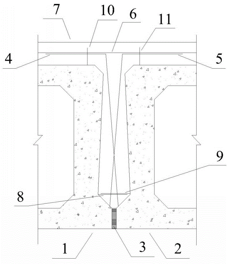
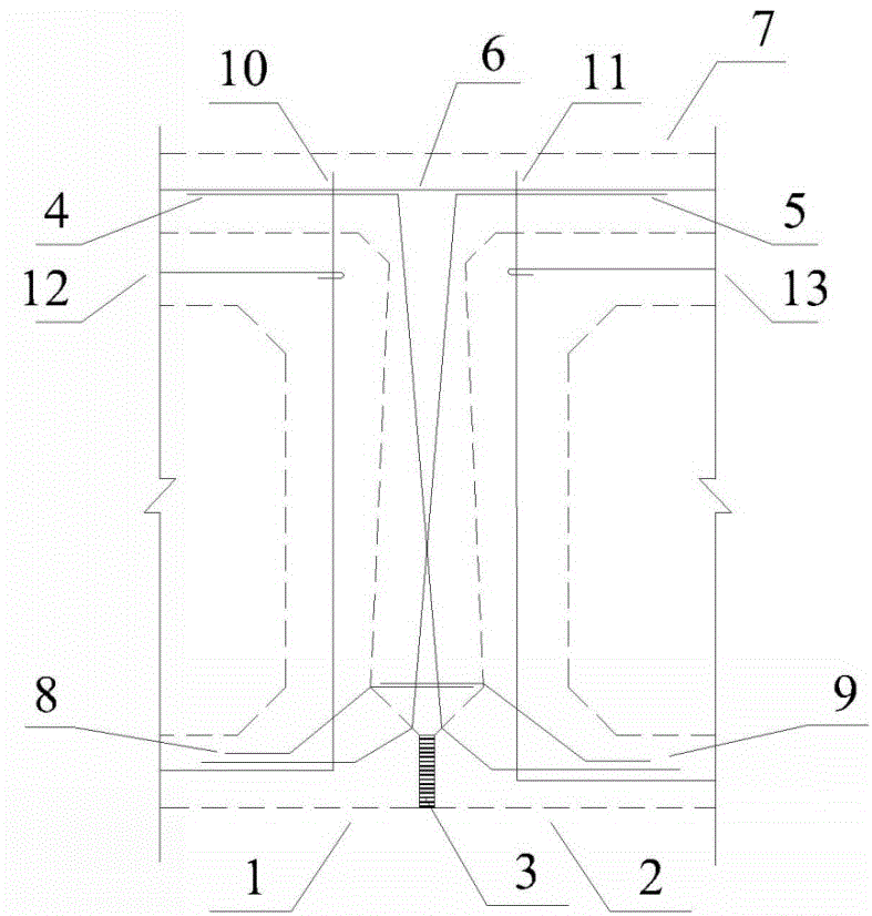
[0027] A schematic cross-section of a hinged joint structure of a hollow slab bridge and a schematic diagram of its reinforcement arrangement are shown in figure 1 and figure 2 . The two adjacent hollow plates include the hollow plate (1) on the left side of the hinged joint and the hollow plate (2) on the right side of the hinged joint. It is filled with elastic sealant. The horizontal connecting steel bar (8) protruding from the seam between the protrusion of the left hollow plate and the web overlaps with the horizontal connecting steel bar (9) protruding from the joint between the protrusion of the hollow plate and the web on the right, and their respective The distance between the front end and the root of the other party (that is, the junction between the bump and the web) is 1 cm. The root of the obliquely connecting steel bar (4) protruding from the hollow slab bump on the right side of the hinge joint and the obliquely connecting steel bar (5) protruding from the ...

Embodiment 2

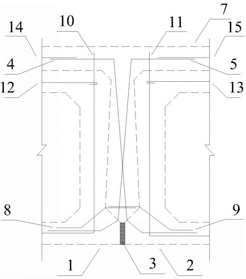
[0029] This implementation example is an amendment to the implementation example 1. For the relevant reinforcement layout diagram, see image 3(The transverse reinforcement in the deck pavement is not shown in this figure). The gap (3) between the lower end bumps of adjacent hollow plates is filled with a two-component chemical slurry, which reacts after mixing, and the volume expands rapidly during the reaction process, and the formed elastic sealing material has internal stress inside, which is called The material is expanded polymer. Place the reinforcement section (14) above the left hollow slab connected to the cross reinforcement and the reinforcement section (15) connected to the cross reinforcement above the right hollow slab above the top slab of the hollow slab at the same height as the reinforcing bars in the pavement. The horizontal section of the cross reinforcement is welded to the section of the reinforcement. The bottom of the cross reinforcement is welded in...

Embodiment 3

[0031] This embodiment is also a modification to Embodiment 1, and the relevant reinforcement layout schematic diagram is shown in Figure 4 . In order to facilitate construction and transportation, and to avoid too much corrosion due to the exposure of cross steel bars, and increase the workload of rust removal, the oblique connecting steel bar (4) protruding from the hollow plate bump on the right side of the hinge joint and the hollow plate on the left side of the hinge joint The oblique connecting steel bar (5) protruding from the bump only stretches out 25 centimeters of the bump when the hollow slab is prefabricated, and is connected with the rest of the cross reinforcement sections by a sleeve before installation on the construction site. Use the horizontal steel bar (12) on the left side of the hollow slab roof and the horizontal steel bar (13) on the right side of the hollow slab roof in the prefabricated hollow slab as the connecting steel bars connecting the crossin...


PUM


Abstract

The invention discloses a hinge joint connecting structure of a hollow slab bridge, and belongs to the field of bridge engineering. Elastic sealing materials formed by the solidification of poured chemical grouts are in a gap of lugs at the lower ends of hollow slabs; connecting reinforcing bars in the hinge joint comprise horizontal connecting reinforcing bars and cross connecting reinforcing bars; each of the horizontal connecting reinforcing bars extends out from the hinge joints of the lugs and a web plate; and each of the cross connecting reinforcing bars extends out from the upper surface of the corresponding lug; and the connecting reinforcing bars extend upwards towards adjacent hollow slabs and are connected with lateral reinforcing bars of the bridge. According to the hinge joint connecting structure disclosed by the invention, cracking and expanding upwards of a longitudinal crack along the bottom of the hinge joint can be delayed; and besides, under the action of the load of an overload vehicle, even hinge joint concrete is separated from the external surface of the web plate of the hollow slab or destroyed after being sheared, the cross oblique connecting reinforcing ribs can still transmit the load of the hollow slab on which wheels are located to the adjacent hollow slabs, and accident that the hollow slab and the vehicle fall off from the bridge after the hollow slab cracks is avoided. The hinge joint connecting structure disclosed by the invention is convenient to construct, low in construction cost, high in functions and has the function of early warning.

Description

technical field [0001] The invention relates to a hinge joint connection structure of a hollow slab bridge, which belongs to the field of bridge engineering. Background technique [0002] In the small span range of less than 20 meters, the bridge type is mostly hollow slab bridge. The main reason is that the hollow slab bridge is constructed by the prefabricated assembly method. The prefabricated quality of the hollow slab is guaranteed, and the assembly construction speed is faster and more economical. However, with the increase of traffic volume on the road and the increase of overloaded vehicles, the hinge joints of the hollow slab bridge will be damaged. The general manifestation is that the bottom of the hinge joint cracks first, weakening the connection between the hollow slabs, and the concrete of the hinge joint is damaged. Rainwater infiltrates into the hinge joints from the bridge deck, which further aggravates the corrosion of steel bars and the deterioration of...

Claims


Application Information

Patent Timeline
Patent Type & Authority Applications(China)
IPC IPC(8): E01D19/12
Inventor 魏建东王利
Owner ZHENGZHOU UNIV
Learn More