Accurate combustion control system

A combustion system and precise control technology, applied in the control of combustion, combustion chamber, combustion method, etc., can solve the problems of insufficient combustion of organic macromolecules, increased content of combustibles in flue gas, low combustion efficiency, etc., to achieve clean combustion, The effect of reducing combustible content and improving combustion efficiency

Inactive Publication Date: 2016-11-23
常滏源 +2
View PDF8 Cites 0 Cited by
  • Summary
  • Abstract
  • Description
  • Claims
  • Application Information

AI Technical Summary

Problems solved by technology

[0004] At present, boilers usually only focus on heat exchange, that is, a heat exchange layer is directly installed on the inner wall of the main combustion chamber for heat exchange, or a heat exchange layer is installed inside or outside the refractory layer on the inner wall of the main combustion chamber for heat exchange, so that the combustion chamber The furnace temperature is very low, causing the organic macromolecules that need to be cracked and burned under high temperature conditions cannot be fully burned, and the combustion efficiency is low; the content of combustibles in the flue gas is increased, causing environmental pollution; and in order to avoid the pollution caused by flue gas emissions Environmental pollution requires filtering or recycling of flue gas, increasing coal energy consumption

Method used


Image

  • Accurate combustion control system
  • Accurate combustion control system
  • Accurate combustion control system

Examples


Embodiment 1

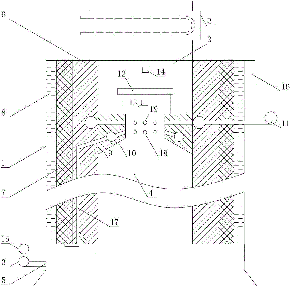
[0013] Embodiment 1: as figure 1 and figure 2 As shown, the combustion system is accurately controlled, which includes a top opening, a hollow combustion device body 1 and a heat exchanger 2, the top opening of the combustion device body 1 is the smoke exhaust port 3; the inner cavity of the combustion device body 1 is the combustion chamber 4 The bottom of the combustion device main body 1 is provided with an air inlet 5 communicating with the combustion chamber 4; the smoke exhaust port 3 is communicated with the heat exchanger 2; Heat layer 8; an auxiliary combustion device 9 is provided in the combustion chamber 4 above; the auxiliary combustion device 9 includes a heat collecting cylinder 10 with upper and lower openings and a hollow interior, a cooling fan 11, a combustion-supporting plate 12, a temperature sensor 13, and CO content detection instrument 14, air supply blower 15 and precise combustion controller 16; the outer wall of the heat collecting cylinder 10 and ...

Embodiment 2

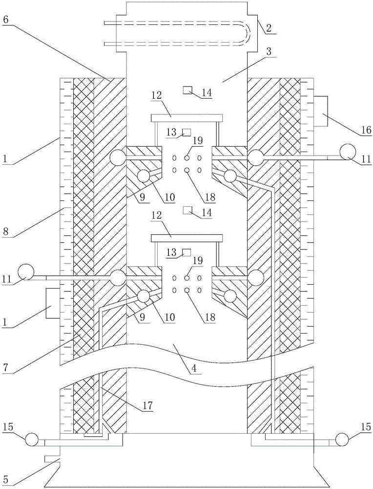
[0015] Embodiment 2: as figure 2 and image 3 As shown, the combustion system is accurately controlled, which includes a combustion device body 1 with a top opening and a hollow interior and a heat exchanger 2. The top opening of the combustion device body 1 is a smoke exhaust port 3; the inner cavity of the combustion device body 1 is a combustion chamber 4 The bottom of the combustion device main body 1 is provided with an air inlet 5 communicating with the combustion chamber 4; the smoke exhaust port 3 is communicated with the heat exchanger 2; Thermal layer 8; two auxiliary combustion devices 9 are arranged up and down in the combustion chamber 4 above, the auxiliary combustion device 9 below is a primary auxiliary combustion device, and the auxiliary combustion device 9 above is a secondary auxiliary combustion device; each auxiliary combustion device The combustion device 9 includes a heat-gathering cylinder 10 with upper and lower openings and a hollow interior, a coo...


PUM


Abstract

The invention discloses an accurate combustion control system which comprises a top opening, a combustion device body and a heat exchanger, wherein the interior of the combustion device body is hollow. The top opening of the combustion device body serves as a smoke vent. An inner cavity of the combustion device body serves as a combustion chamber. The smoke vent communicates with the heat exchanger. A shell of the combustion device body sequentially comprises a refractory layer, a heat preservation layer and a heat exchange layer from inside to outside. One or more auxiliary combustion devices are vertically arranged in the upper portion of the combustion chamber. The accurate combustion control system has the advantages that different from the mode that heat exchange is conducted in a combustion chamber of a traditional boiler, the heat preservation layer is arranged on the outer side of the refractory layer, heat in the combustion chamber cannot be dissipated easily, the temperature in the combustion chamber is effectively guaranteed, organic macromolecules which can be split and combusted only under the high-temperature condition are combusted sufficiently, the heat exchange layer on the outer side of the heat preservation layer sufficiently absorbs heat dissipated by the heat preservation layer, and the combustion efficiency of a boiler and the combustion utilization rate of coal are improved while the thermal conversion efficiency is guaranteed.

Description

Technical field: [0001] The invention relates to a precise control combustion system, belonging to a coal-fired boiler. Background technique: [0002] The existing theory of secondary combustion of flue gas from coal-fired boilers is to add a large amount of air to the flue gas to recombust the high ignition point combustibles in the flue gas and a small amount of carbon monoxide produced by the combustion of coal under anoxic conditions. However, according to the latest combustion theory proposed by Tsinghua University: Coal is also anoxic combustion under oxygen-rich conditions, which will produce a large amount of CO. On the basis of this theory, it can be seen that the existing coal-fired boiler flue gas secondary combustion method actually reduces the concentration of CO, so that CO cannot be fully burned. [0003] At the same time, coal and petrochemical organic fuels are complex organic macromolecules, some of which require higher temperatures for cracking and combus...

Claims


Application Information

Patent Timeline
Patent Type & Authority Applications(China)
IPC IPC(8): F23B90/06F23L1/00F23L15/00F23M5/08F23N5/00F23N5/02
CPCF23B7/002F23B90/06F23L15/00F23L2900/15043F23M5/08F23N5/003F23N5/02Y02E20/34
Inventor 常滏源爱因常青
Owner 常滏源
Why Eureka
Try Eureka