Gas sensor

A gas sensor and sensor element technology, applied in instruments, scientific instruments, and material analysis using sound waves/ultrasonic waves/infrasonic waves, etc., can solve problems such as limiting fast calibration and fast measurement, and achieve small thermal mass, high duty cycle, Effect of Reducing Power Consumption

Active Publication Date: 2016-11-23
INFINEON TECH AG +1
View PDF5 Cites 0 Cited by
  • Summary
  • Abstract
  • Description
  • Claims
  • Application Information

AI Technical Summary

Problems solved by technology

Therefore, the possibility of fast calibration and fast measurement is limited

Method used


Image

  • Gas sensor
  • Gas sensor
  • Gas sensor

Examples


Embodiment Construction

[0038] In the following description of the figures, identical or identically acting elements are assigned the same reference numerals, so that their descriptions can be interchanged with one another in the different exemplary embodiments.

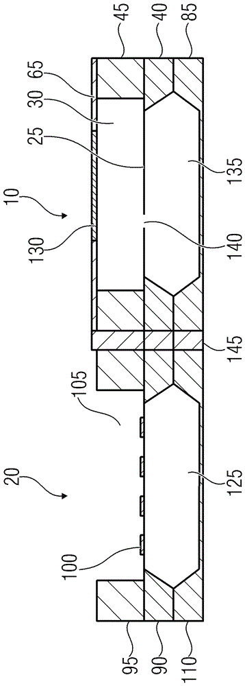
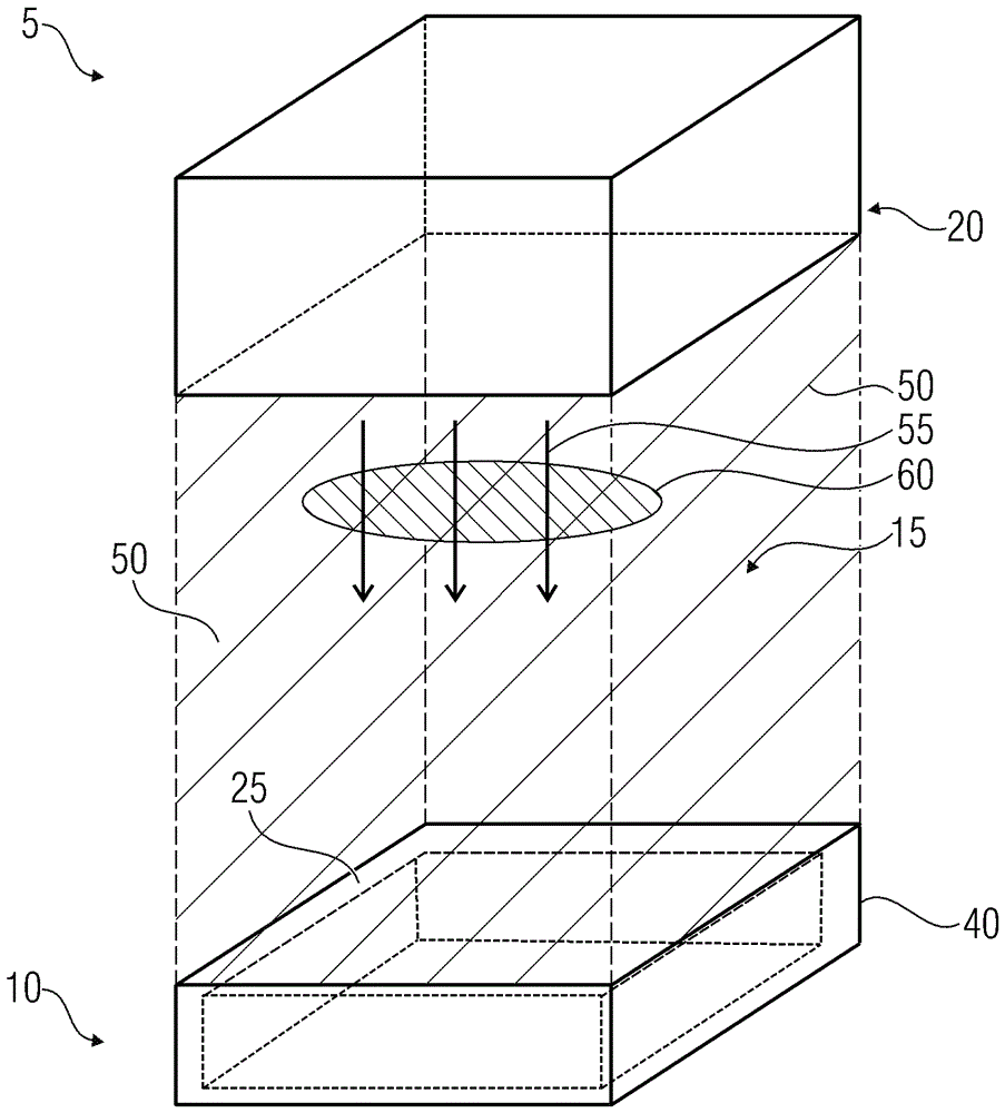
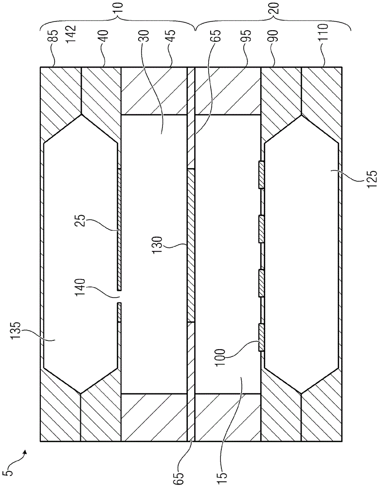
[0039] FIG. 1 a shows a gas sensor 5 with a sensor element 10 , a measuring chamber 15 and an emitter element 20 . The sensor element 10 has a MEMS membrane 25 which is arranged in a first substrate region 40 . The measuring chamber 15 is designed to accommodate a measuring gas 50 . Furthermore, according to one embodiment, the sensor element 10 and the emitter element 20 can have a hermetically closed connection such that a hermetically closed measuring chamber 15 is formed. This can prolong the lifetime of the emitter element 20 or the entire gas sensor since it operates in a protective atmosphere. The same effect can also be achieved by a housing surrounding the gas sensor. The MEMS membrane forms, for example, a micromechanical capac...


PUM


Abstract

Shown is a gas sensor 5 including a sensor element 10, a measurement chamber 15 and an emitter element 20. The sensor element 10 has a MEMS membrane 25 which is arranged in a first substrate region 40. Furthermore, the measurement chamber 15 is embodied to receive a measurement gas 50.

Description

technical field [0001] The present invention describes a gas sensor with a MEMS membrane. The embodiment shows a PAS (Photo Acoustic Sensor) module utilizing a MEMS (Micro Electro Mechanical System) multi-chip solution. Background technique [0002] MEMS devices, also known as microelectromechanical systems, are often used as sensors, such as acceleration sensors, pressure sensors or acoustic wave sensors (microphones). All these MEMS devices have a movable element, such as a diaphragm or a cantilever, wherein a movement of the movable element, eg due to a pressure change or acceleration, can be detected capacitively. Thus, a common variant of a MEMS device includes a movable electrode as the movable element and a fixed electrode opposite the movable electrode such that a change in the distance between the two electrodes (due to movement of the movable element) can result in Capacitance changes. [0003] Gas sensor systems to date have utilized components with dimensions ...

Claims


Application Information

Patent Timeline
Patent Type & Authority Applications(China)
IPC IPC(8): G01N21/17
CPCG01N21/1702G01N2021/1704G01N29/2418G01N29/022G01N29/30G01N2291/0256
Inventor A.德赫J.胡贝尔F.约斯特S.科尔布H.托伊斯W.魏德迈尔J.韦伦施泰因
Owner INFINEON TECH AG
Why Eureka
Try Eureka