Battery Shell Structure
A layered structure and battery shell technology, applied in structural parts, battery pack parts, battery boxes/coats, etc., can solve problems such as battery bursting and reduced battery life, so as to prolong service life, improve shielding, and enhance safety sexual effect
- Summary
- Abstract
- Description
- Claims
- Application Information
AI Technical Summary
Problems solved by technology
Method used
Image

Examples
no. 1 example
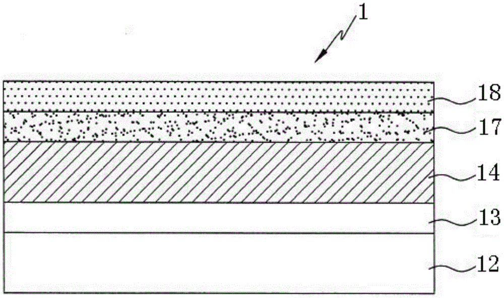
[0039] Please refer to the attached figure 1 , which is a schematic cross-sectional structure diagram of the first embodiment of the battery shell structure 1 of the present invention, the battery shell structure 1 includes an inner cladding layer 12, a gas barrier layer 14, and a free radical capture adhesive layer 17 stacked in sequence And outer protective layer 18.
[0040] In this embodiment, a first adhesive layer 13 is also provided between the inner coating layer 12 and the gas barrier layer 14, and the first adhesive layer 13 is used to bond the inner coating layer 12 to the gas barrier layer 14. above the gas barrier layer 14.
[0041] In this embodiment, the free radical scavenging adhesive layer 17 includes an adhesive and a free radical scavenging agent. The free radical scavenger is a compound used to provide free hydrogen, wherein the compound with the main structure of the aromatic ring having a hydroxyl group is preferred, and the compound has free hydrogen ...
no. 2 example
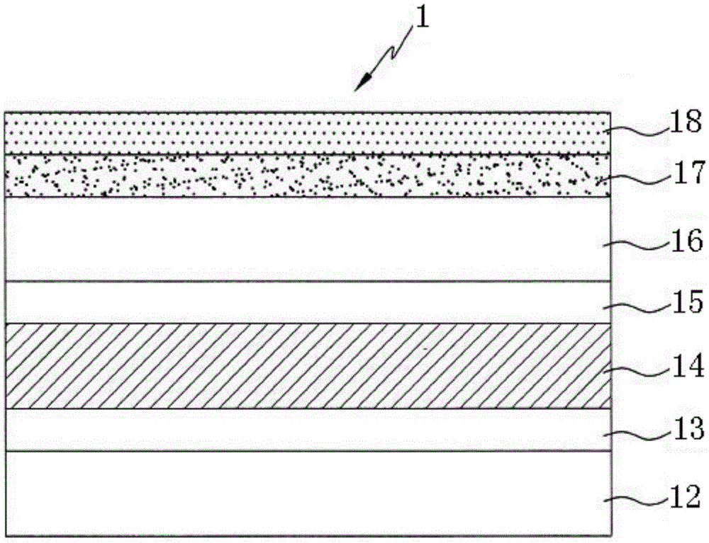
[0052] Please refer to the attached image 3 , which is a schematic cross-sectional structure diagram of the second embodiment of the battery shell structure 1 of the present invention, the difference from the battery shell structure shown in the first embodiment is that the battery shell structure shown in the second embodiment Among them, a heat-resistant layer 16 is also included, and the heat-resistant layer 16 is formed between the gas barrier layer 14 and the radical capture adhesive layer 17 .
[0053] In this embodiment, the heat-resistant layer 16 is adhered to the gas barrier layer 14 through the second adhesive layer 15, so that the heat-resistant layer 16 is sandwiched between the free radical capture adhesive layer 17 and the second adhesive layer 15.
[0054] The heat-resistant layer 16 has a thickness of 10-50 microns, and its material can be selected from polyamide, polyester, or polyimide.
[0055] The preparation method of the battery shell structure of the...
Embodiment 1
[0056] Embodiment 1: The preparation method of the battery shell structure shown in the first embodiment of the present invention
[0057] The battery shell structure 1 includes an inner cladding layer 12, the inner cladding layer 12 adopts a polypropylene film (Nanya, CXDA) with a thickness of 40 micrometers (μm), and a polyurethane resin is arranged on the inner cladding layer 12 (Asia Electric Materials Company, model AEM-A1) to form a 4 μm thick first adhesive layer 13, use 40 μm thick aluminum foil as the gas barrier layer 14, and stick the gas barrier layer 14 through the first adhesive layer 13 Connected to the inner cladding layer 12, and then form a 4 μm thick free radical capture adhesive layer 17 on the gas barrier layer 14, wherein the free radical capture adhesive layer 17 includes polyurethane resin (Asia Electric Materials Co., Ltd., Model AEM-A1), and free radical scavenger (N, N'-bis (2-naphthyl) p-phenylenediamine, Tianqing Chemical, model anti-aging agent DN...
PUM
| Property | Measurement | Unit |
|---|---|---|
| Thickness | aaaaa | aaaaa |
| Thickness | aaaaa | aaaaa |
| Thickness | aaaaa | aaaaa |
Abstract
Description
Claims
Application Information
 - R&D
- Intellectual Property
- Life Sciences
- Materials
- Tech Scout
- Unparalleled Data Quality
- Higher Quality Content
- 60% Fewer Hallucinations
Browse by: Latest US Patents, China's latest patents, Technical Efficacy Thesaurus, Application Domain, Technology Topic, Popular Technical Reports.
© 2025 PatSnap. All rights reserved.Legal|Privacy policy|Modern Slavery Act Transparency Statement|Sitemap|About US| Contact US: help@patsnap.com