
An intensive DC ice-melting system for 500kv substation with svg function

A technology of DC ice melting and substation, which is applied in the installation of flexible AC power transmission system, electrical components, cables, etc. It can solve the problems of high temperature, need for deionization treatment, affect device reliability, and heavy maintenance workload, etc., to meet the requirements of High reliability and dynamic reactive power compensation requirements, optimization of dynamic reactive power and static reactive power coordination, and the effect of reducing device volume and cost

Active Publication Date: 2017-11-28
STATE GRID HUNAN ELECTRIC POWER +2
View PDF4 Cites 0 Cited by
  • Summary
  • Abstract
  • Description
  • Claims
  • Application Information

AI Technical Summary

Problems solved by technology

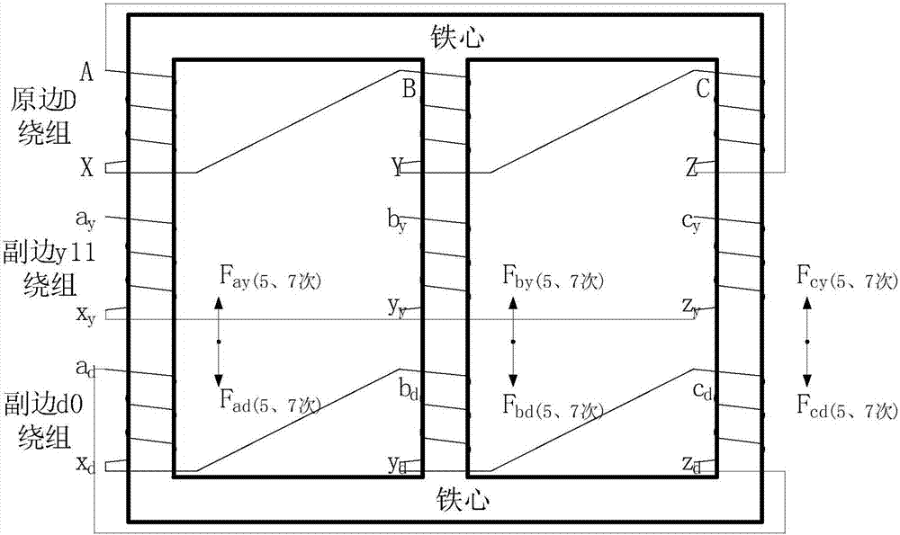
However, this type of device has the following technical problems: Problem 1, large harmonics, large footprint: when the device is running, it will generate a large number of 5th and 7th harmonic currents, and the device itself and the filter need to be equipped with multiple sets of large-capacity capacitors, Reactor, resulting in a large area of ​​the device and high construction costs; problem 2, ice melting and reactive power compensation must be configured with the same capacity: the overall capacity should take into account both the SVG and the ice melting device, the voltage is the high voltage of the SVG, and the current is the ice melting device The high current leads to a very large overall capacity and high cost; problem 3, the heat generation is large, and water cooling must be used: this method has large losses and high operating costs, so water cooling must be used, and a water cooling system must be added. The water quality requirements are high, and deionization is required At the same time, it is necessary to prevent water leakage, and antifreeze treatment is required in winter, and the maintenance workload is heavy, which affects the reliability of the device

Method used


Image

  • An intensive DC ice-melting system for 500kv substation with svg function
  • An intensive DC ice-melting system for 500kv substation with svg function
  • An intensive DC ice-melting system for 500kv substation with svg function

Examples


Embodiment Construction

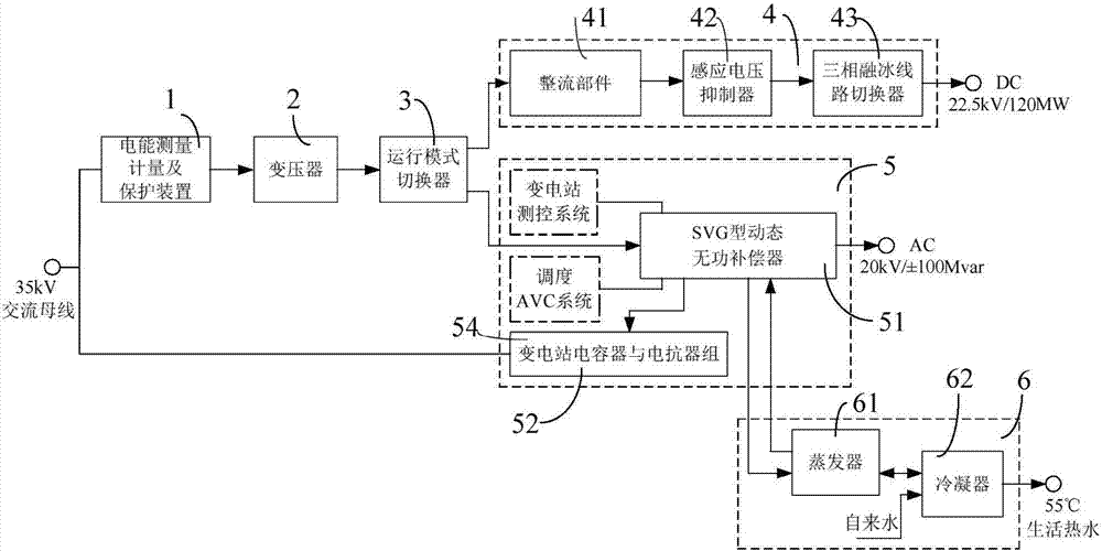
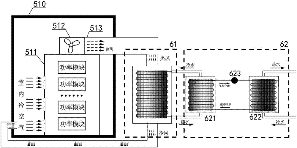
[0021] Such as figure 1 As shown, the 500kV substation intensive DC ice-melting system with SVG function in this embodiment includes an electric energy measurement and protection device 1, a transformer 2, an operation mode switcher 3, a DC ice-melting unit 4 and a dynamic reactive power compensation unit 5, The primary side of the transformer 2 is connected to the 35kV AC bus of the substation through the electric energy measurement and protection device 1 , and the secondary side of the transformer 2 is connected to the DC deicing unit 4 and the dynamic reactive power compensation unit 5 through the operation mode switch 3 respectively. In this embodiment, the output terminal of the transformer 2 after stepping down the 35kV high voltage is connected to the input terminal of the operation mode switcher 3, and the output terminal of the operation mode switcher 3 is respectively connected to the input terminals of the DC ice melting unit 4 and the dynamic reactive power compens...


PUM


Abstract

The invention discloses a 500kV substation intensive DC ice-melting system with SVG function, which includes electric energy measurement and protection device, transformer, operation mode switcher, DC ice-melting unit and dynamic reactive power compensation unit. The primary side is connected to the AC bus of the substation through an electric energy measurement and protection device, and the secondary side of the transformer is connected to a DC ice-melting unit and a dynamic reactive power compensation unit through an operation mode switcher. The invention can realize the recovery and utilization of the heat loss of the device itself, is compatible with the dispatching AVC system of the substation, provides effective guidance for the research on the multifunctional topology of the ice melting device and the development of the device, and is widely applicable to 500kV substations.

Description

technical field [0001] The invention relates to an ice-melting device for electrical engineering, in particular to an intensive DC ice-melting system for a 500kV substation with SVG functions. Background technique [0002] Ice and snow disasters occur frequently in southern regions such as Guizhou, Hunan, and Hubei in China. Due to abnormal climate changes in recent years and even northern regions such as Beijing and Liaoning, ice and snow disasters also occur from time to time. After the transmission line is covered with ice, it is easy to cause tower collapse and disconnection, which seriously threatens the power grid. Safe and stable operation and power supply reliability. In order to improve the ability of transmission lines to resist ice disasters, many domestic units have developed various types of DC ice-melting devices, which provide a solid technical guarantee for the safe and stable operation of the power grid in winter, but the ice-melting devices are only used du...

Claims


Application Information

Patent Timeline
Patent Type & Authority Patents(China)
IPC IPC(8): H02G7/16H02J3/18
CPCH02G7/16H02J3/18Y02E40/10
Inventor 陆佳政朱思国李波谭艳军周秀冬朱远黄清军
Owner STATE GRID HUNAN ELECTRIC POWER
Learn More