Uniform energy storage and conversion control system

A technology of energy storage and conversion control, which is applied to AC network circuits, electrical components, and AC networks to reduce harmonics/ripples, etc. It can solve problems such as high cost of source filtering, rising catenary voltage, and grid impact, etc., to achieve Effects of improving safety and stability, suppressing high-order harmonic resonance, and reducing current and loss

Active Publication Date: 2016-11-23
湖南华大紫光科技股份有限公司
View PDF4 Cites 21 Cited by
  • Summary
  • Abstract
  • Description
  • Claims
  • Application Information

AI Technical Summary

Problems solved by technology

At present, the regenerative braking energy of the electric locomotive is generally fed back directly to the grid, which will cause the voltage of the catenary to rise, and may cause the protection of the traction substation to malfunction and cause an impact on the grid
[0003] In addition, with the rapid development of electrified railways in my country, power quality problems such as negative sequence, reactive power, harmonics, and feeder voltage fluctuations and deviations caused by electrified railway load characteristics and traction transformer wiring types have become increasingly prominent. These problems not only affect The normal operation of the traction power supply system also brings hidden dangers to the safe and stable operation of the power grid
The methods to control high-order harmonics mainly include passive filtering and active filtering (APF). The cost of source filtering is high, and the loss of passive filtering is large. Therefore, there is still a lack of economical and effective treatment methods for high-order harmonic resonance problems in electrified railways.
The control of reactive power and feeder voltage fluctuations and deviations mainly uses dynamic var compensator (SVC) and static var generator (SVG). Solve the problem of feeder voltage fluctuation and deviation
The railway power conditioner (RPC) can comprehensively solve the negative sequence and reactive power problems, but it is difficult to efficiently solve the problem of regenerative braking energy utilization. Although RPC can transfer regenerative braking energy from one power supply arm to another power supply arm, due to Without a large-capacity energy storage device, if there is no traction load on the power supply arm that receives the energy, regenerative braking energy cannot be used efficiently, and in the end it can only be fed back to the grid, causing waste and impact, and it is difficult to meet the needs of railway users

Method used


Image

  • Uniform energy storage and conversion control system
  • Uniform energy storage and conversion control system
  • Uniform energy storage and conversion control system

Examples


Embodiment 1

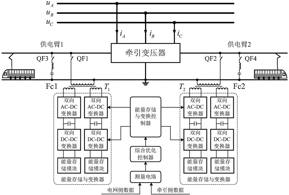
[0045] Example 1, such as figure 1 As shown, a unified energy storage and conversion control system according to the first embodiment of the present invention includes:

[0046] The single-phase multi-winding isolation transformer is connected to the power supply arm of the traction transformer and isolates and reduces the voltage. Two single-phase multi-winding isolation transformers T 1 And T 2 The high-voltage side is connected to a power supply arm of the traction transformer through the connection switches QF1 and QF2, T 1 And T 2 The low-voltage side includes at least one low-voltage winding.

[0047] Energy storage and converter, which is used to store and release the regenerative braking energy of the traction locomotive in real time, store electricity when there is no traction load, charge and store energy during valley priority, discharge energy during peak time, and compensate for the reactive power of the power supply arm power. The input sides of the two energy stora...

Embodiment 2

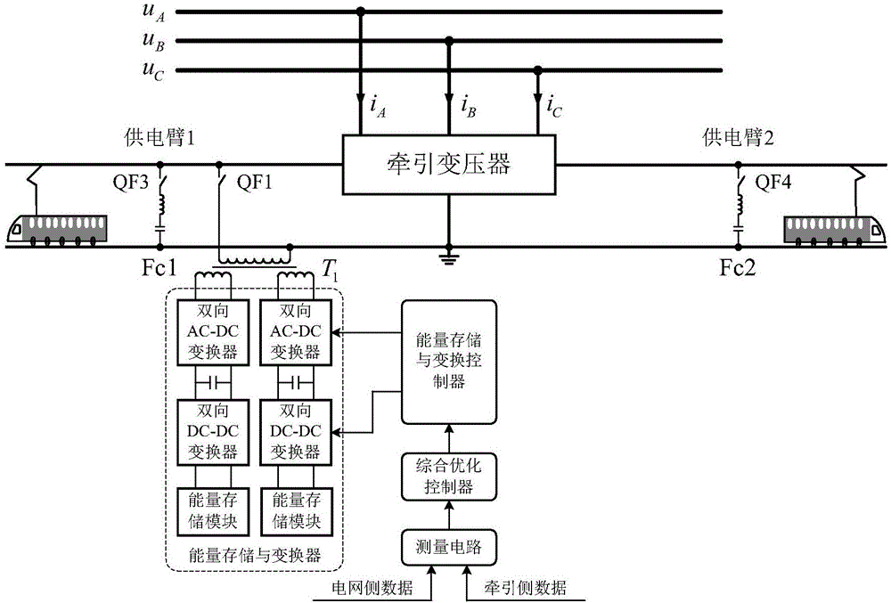
[0054] Example 2, such as figure 2 As shown, a unified energy storage and conversion control system according to the second embodiment of the present invention. The difference from the first embodiment is that it includes a single-phase multi-winding isolation transformer T 1 And an energy storage and converter. A single-phase multi-winding isolation transformer T 1 The high-voltage side is connected to a power supply arm of the traction transformer through the connection switch QF1, T 1 The low-voltage side includes at least one low-voltage winding.

[0055] An energy storage and converter input side and single-phase multi-winding isolation transformer T 1 The corresponding secondary winding is connected. The energy storage and converter includes two energy storage and conversion sub-modules, and the input side of each energy storage and conversion sub-module is connected to a single-phase multi-winding isolation transformer T 1 The corresponding secondary winding. The energy ...

Embodiment 3

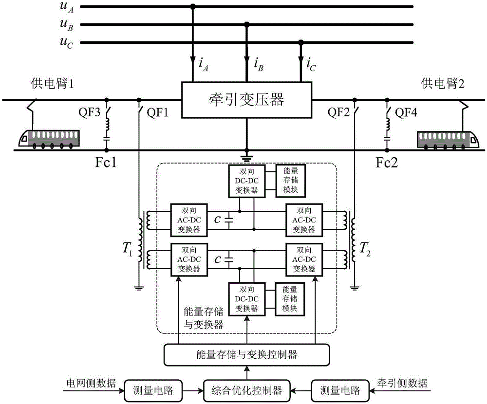
[0056] Example 3, such as image 3 As shown, a unified energy storage and conversion control system according to the third embodiment of the present invention. The difference from the first embodiment is that it includes two single-phase multi-winding isolation transformers T 1 , T 2 And an energy storage and converter. The input side of energy storage and converter and T 1 , T 2 The corresponding secondary winding is connected. The energy storage and converter includes two energy storage and conversion sub-modules. The input sides of the two energy storage and conversion sub-modules are respectively connected to a single-phase multi-winding isolation transformer T 1 And T 2 The corresponding secondary winding. Among them, the energy storage and conversion sub-module includes two bidirectional AC-DC converters, a capacitor, a bidirectional DC-DC converter and an energy storage module, the AC side of a bidirectional AC-DC converter and a single-phase multi-winding The secondary...


PUM


Abstract

The invention discloses a uniform energy storage and conversion control system. The system comprises a single-phase multi-winding isolation transformer, an energy storage and conversion device, a measurement circuit, a comprehensive optimization controller and an energy storage and conversion controller, wherein the single-phase multi-winding isolation transformer is connected with a power supply arm; the input side of the energy storage and conversion device is connected with a secondary-line winding, the energy storage and conversion device comprises at least one energy storage and conversion submodule, and each submodule comprises at least one two-way AC-DC converter, a two-way DC-DC converter and an energy storage module; the measurement circuit is connected with the power grid side and the traction side; the comprehensive optimization controller is connected with the measurement circuit; the energy storage and conversion controller is connected with the comprehensive optimization controller, the two-way AC-DC converter and the two-way DC-DC converter. The invention further provides a comprehensive optimization control method for the uniform energy storage and conversion control system. The uniform energy storage and conversion control system has the advantages that regenerative brake energy of a traction engine is stored and used in real time, charging energy storage during the valley time period and discharging energy supply during the peak time period are carried out preferentially, peak clipping and valley filling and demand side response management are achieved, power supply capacity is improved, and cost is reduced; negative sequence, idle work, harmonic wave, voltage fluctuation and deviation management is achieved.

Description

Technical field [0001] The invention relates to the technical field of electrified railways, in particular to a unified energy storage and conversion control system. Background technique [0002] At present, my country's electric locomotives generally adopt two braking methods: energy consumption braking and regenerative braking. Energy consumption braking is mainly used for AC-DC locomotives, and regenerative braking is mainly used for AC-DC-AC locomotives. With the development of high-speed and heavy-load electrified railways in my country, AC, DC, and AC locomotives have become the main development direction. Due to the large power of regenerative braking, how to deal with regenerative braking energy has become a problem that cannot be ignored. At present, the regenerative braking energy of electric locomotives is generally directly fed back to the grid, which will cause the voltage of the contact grid to rise, and may cause the protection of the traction substation to malfu...

Claims


Application Information

Patent Timeline
Patent Type & Authority Applications(China)
IPC IPC(8): H02J3/32H02J3/01H02J3/18H02J3/00
CPCH02J3/00H02J3/01H02J3/18H02J3/32Y02E40/30Y02E40/40
Inventor 周冠东罗隆福罗培严文交
Owner 湖南华大紫光科技股份有限公司
Why Eureka
Try Eureka