
Air injection apparatus protruding toward seawater from bottom plate of vessel

An air jet and ship technology, applied in jetting device, jetting device, ship hull, etc., can solve the problems of reduced air discharge chamber binding force, corrosion, inability to polish the surface, etc., to improve watertightness and airtightness, and improve corrosion resistance. , the effect of reducing frictional resistance

Active Publication Date: 2016-11-23
HYUNDAI HEAVY IND CO LTD
View PDF8 Cites 3 Cited by
  • Summary
  • Abstract
  • Description
  • Claims
  • Application Information

AI Technical Summary

Problems solved by technology

[0005] The method has the problem of having to reinforce the structure around the hole due to drilling a plurality of air holes in the bottom surface of the ship, and inconvenience in maintenance due to an increase in the cleaning area, and because of There is a chamber inside, so there is a problem that the volume of the chamber is reduced, etc.
[0006] In addition, existing air discharge chambers are limited by their shape, so it is not possible to weld the inside of the air discharge chamber to the bottom plane, even if only the edge of the air discharge chamber is welded or even the inside of the edge is welded by a fillet weld , it is also impossible to get close to the inner surface after welding, so that the surface cannot be polished, or even if the blasting method is used to perform the inner surface grinding operation on the dry site, it will be difficult to approach the inner surface for coating. problem, thereby reducing the binding force of the air discharge chamber to the bottom surface of the ship, thereby predicting that as the service time of the ship increases, continuous damage occurs, in other words, the problem of susceptibility to corrosion caused by seawater arises
[0007] In addition, in order to reduce the frictional resistance and prevent biofouling on the bottom part of the ship in contact with seawater, and to prevent the deterioration of fuel efficiency due to biofouling, antifouling paint is painted, or the existing ones installed on the bottom surface of the ship Due to the limitation of the shape of the air discharge chamber, it is difficult to grind the surface of the ship's bottom surface for painting treatment after edge welding, so there is a problem in that it is expected that the paint will peel off after the painting treatment. And produce serious corrosion phenomenon caused by seawater, etc.

Method used


Image

  • Air injection apparatus protruding toward seawater from bottom plate of vessel
  • Air injection apparatus protruding toward seawater from bottom plate of vessel
  • Air injection apparatus protruding toward seawater from bottom plate of vessel

Examples


Embodiment Construction

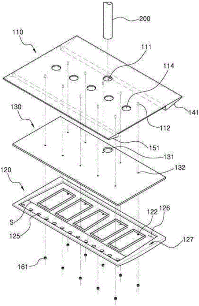
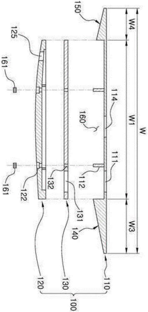
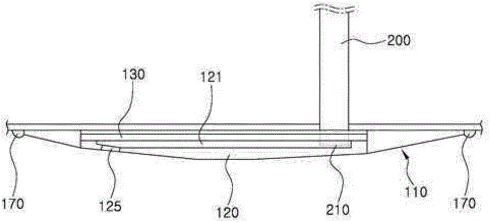
[0050] figure 1 It is an illustration figure (exploded view) showing the structure according to the present invention, figure 2 is an illustration diagram showing a combination relationship according to the present invention, image 3 It is an illustration diagram (combined diagram) showing the constitution according to the present invention, Figure 4 is an illustration showing the composition of the base plate according to the present invention, Figure 5 is an illustration showing the structure of the air injection plate according to the present invention, Image 6 yes means Figure 5 An illustration of the A-A cross-section configuration, Figure 7 is an illustration showing the flow of air in the air flow path according to the present invention, Figure 8 is an illustration showing the composition of the connecting plate according to the present invention, Figure 9 It is an illustration of the bottom surface of a ship showing the installation state of the present ...


PUM


Abstract

The present invention relates to an air injection apparatus that protrudes toward the seawater from the bottom plate of a vessel. The objective of the present invention is to achieve easy installation and assembly / disassembly of the air injection apparatus on the bottom surface of a vessel, to enhance water tightness for an air path, to enhance bubble generation efficiency by air injection into the seawater, and to efficiently reduce frictional resistance of the vessel by forming a bubble layer along the bottom surface of the vessel. The air injection apparatus, according to the present invention, comprises: an air injection module that is installed to be located on the bottom surface of the bow of a vessel and has a plurality of air paths and air injection holes formed therein, the plurality of air injection holes being formed to communicate with the air paths and the outside thereof; and an air supply structure that is installed to be connected to the air injection module while passing through the bottom of the vessel and supplies air into the air paths of the air injection module, wherein the air injection module includes: a base plate that is installed on the bottom surface of the vessel through welding and through which the air supply structure is installed to pass; an air injection plate that is coupled to a positioning part of the base plate and has an air path and a plurality of air injection holes formed therein, wherein the air path communicates with the air supply structure, and the plurality of air injection holes communicate with the air path; and a connecting plate that is installed to be located between the base plate and the air injection plate and has a sealing function.

Description

technical field [0001] The present invention relates to an air injection device protruding from the seawater on the bottom plate of the ship, and relates to an air injection device protruding from the sea water on the bottom plate of the ship, which is provided with an air injection module that is easy to separate and combine on the bottom plane of the ship. Air is supplied to the air injection module through the air supply structure, and the air bubbles flow along the bottom of the ship from the bow to the stern to form a bubble layer. Background technique [0002] Usually, when a ship is sailing, the frictional resistance in the water is the most influential among the various resistances that the hull is subjected to. It accounts for about 80% of the overall resistance in low-speed ships and about 50% of the overall resistance in high-speed ships. Caused by the viscosity of the water particles that the hull contacts. [0003] Thus, in order to be able to cut off the visco...

Claims


Application Information

Patent Timeline
Patent Type & Authority Applications(China)
IPC IPC(8): B63B1/38B05B1/02
CPCY02T70/10
Inventor 金敬桓韩范羽
Owner HYUNDAI HEAVY IND CO LTD
Learn More