Cooling device used for solid thermal carrier waste heat utilization system

A solid heat carrier and cooling device technology, which is applied in the field of waste heat recovery and waste heat recovery and utilization of solid heat carriers, can solve the problems of insufficient cooling and cooling of high-temperature solid heat carriers, and achieves promotion of cooling and cooling, heat recovery, and increased airflow disturbance. , the effect of reducing the length

Active Publication Date: 2016-11-30
JIANGSU TAIHU BOILER
View PDF5 Cites 3 Cited by
  • Summary
  • Abstract
  • Description
  • Claims
  • Application Information

AI Technical Summary

Problems solved by technology

[0003] In view of the above problems, the present invention provides a cooling device for the solid heat carrier waste heat utilization system, which can solve the problem that the existing cooling device does not sufficiently cool the high-temperature solid heat carrier

Method used


Image

  • Cooling device used for solid thermal carrier waste heat utilization system
  • Cooling device used for solid thermal carrier waste heat utilization system

Examples


Embodiment Construction

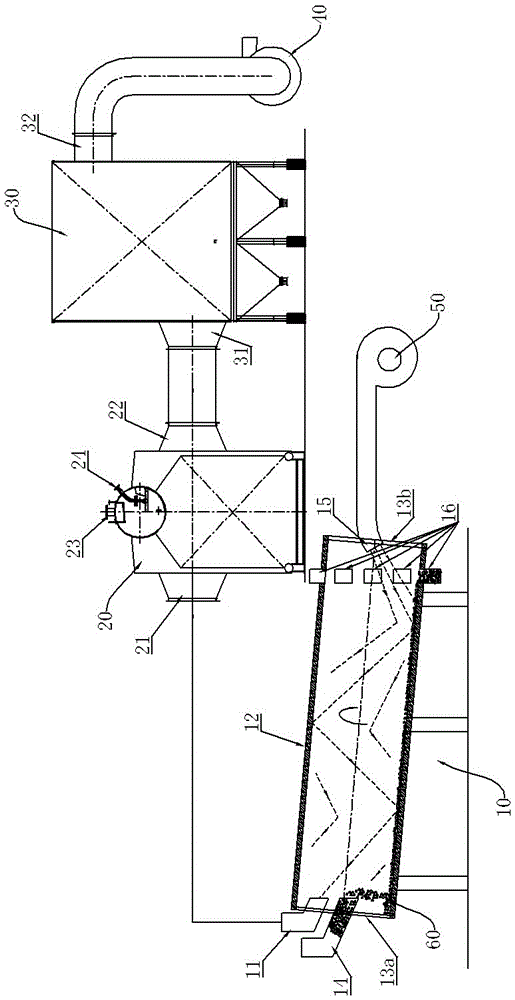
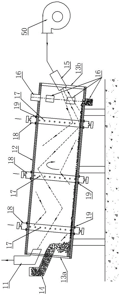
[0014] See figure 2 , the cooling device 10 for the solid heat carrier waste heat utilization system, which includes a rotary kiln 12, the two ends of the rotary kiln 12 are respectively sealed by end covers 13a, 13b and the rotary kiln 12 and the two end covers 13a, 13b can be relatively Turning, the end cover 13a is provided with a heat carrier inlet 14 and a high-temperature flue gas outlet 11, the end cover 13b is provided with a cooling air inlet 15, and the cooling air inlet 15 is connected to the blower 50, and the side of the rotary kiln 12 close to the cooling air 15 inlet is provided with a The heat carrier outlet 16; the outer periphery of the rotary kiln 12 is provided with a number of air inlet holes 17 distributed along the circumferential direction in rows. In this embodiment, three rows of air inlet holes 17 are arranged. Ring-shaped air inlet bins 18 are installed at the positions, and the annular air inlet bins 18 and the rotary kiln 12 can be relatively rot...


PUM


Abstract

The invention provides a cooling device used for a solid thermal carrier waste heat utilization system. The cooling device is capable of solving a problem that cooling of high temperature solid thermal carriers via conventional cooling devices is insufficient. The cooling device comprises a rotary kiln; the two ends of the rotary kiln are sealed with end covers respectively, and the rotary kiln is capable of rotating relative to the two end covers; one of the end covers is provided with a thermal carrier inlet and a high temperature exhaust gas outlet, and the other end cover is provided with a cooling wind inlet; the cooling wind inlet is connected with an air blower; one end of the rotary kiln close to the cooling wind inlet is provided with thermal carrier outlets; the periphery of the rotary kiln is provided with a plurality of air inlets along the circumferential direction in lines; each line of the air inlets on the periphery of the rotary kiln is provided with an annular air inlet cabin; the annular air inlet cabins are capable of rotating relative to the rotary kiln; cooling wind is delivered into the annular air inlet cabins; and an air outlet channel of each annular air inlet cabin is arranged to towards the corresponding line of air inlets on the rotary kiln.

Description

technical field [0001] The invention relates to the technical field of waste heat recovery and utilization, in particular to the field of solid heat carrier waste heat recovery and utilization, in particular to a cooling device for a solid heat carrier waste heat utilization system. Background technique [0002] Usually, a large amount of high-temperature slag and slag are generated in the production process of metal smelting. In the traditional production process, these high-temperature slag and slag are usually cooled down and then discarded directly. On the one hand, it causes waste of resources, and on the other hand, it also causes pollution to the environment. . At present, there is a solid heat carrier waste heat utilization system in this field, see figure 1 , which first cools the high-temperature solid heat carrier through the cooling device 10 and at the same time generates high-temperature flue gas that reaches the rated service temperature. After the dust is r...

Claims


Application Information

Patent Timeline
Patent Type & Authority Applications(China)
IPC IPC(8): C21B3/08
CPCC21B3/08
Inventor 张浩顾利平田忠权徐传香
Owner JIANGSU TAIHU BOILER
Why Eureka
Try Eureka