An air-heating circulation heating type quicksand bed
A technology of circulating heating and quicksand, which is applied to heat storage heaters, fluid heaters, lighting and heating equipment, etc., can solve problems such as infeasibility, and achieve the effect of saving treatment costs and time.
- Summary
- Abstract
- Description
- Claims
- Application Information
AI Technical Summary
Problems solved by technology
Method used
Image
Examples
Embodiment 1
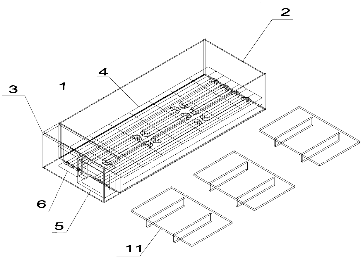
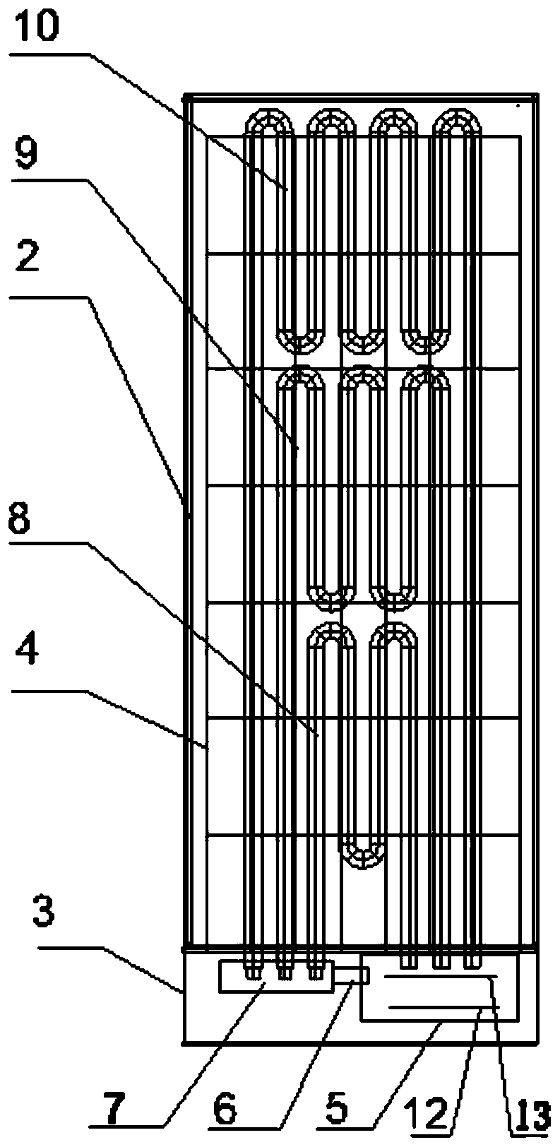
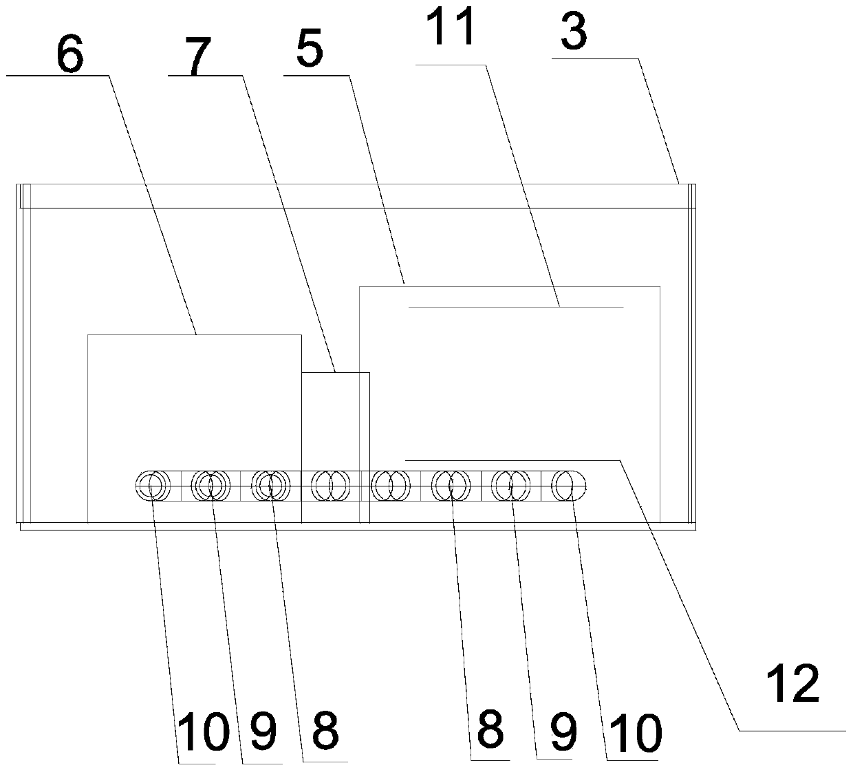
[0053] Such as Figure 1 to Figure 3As shown, a wind-heating circulation heating quicksand bed in this embodiment includes a bed body 1, which is a cuboid, and is divided into a sand treatment area 2 and an equipment area 3 by partitions.
[0054] The sand treatment area 2 is a semi-closed structure with an open top, and a bottom plate 4 is arranged in the sand treatment area 2, and yellow sand is laid on the bottom plate 4 to form a sand pool. A first radiating pipe 8, a second radiating pipe 9 and a third radiating pipe 10 are laid under the bottom plate 4 to heat the sand pool. Wherein, the second heat dissipation pipe 9 is disposed on the side of the first heat dissipation pipe 8 , and the third heat dissipation pipe 10 is disposed on the side of the second heat dissipation pipe 9 .
[0055] Preferably, the first radiating pipe 8 includes an air inlet pipe, an air outlet pipe, two straight pipes and three U-shaped pipes, wherein the air inlet pipe, the air outlet pipe and...
Embodiment 2
[0061] Such as Figure 4 to Figure 6 As shown, the circulating heating type quicksand bed of the present embodiment also includes a sand bath device and a sand return device.
[0062] Wherein, the sand bath device 14 is installed at one end of the sand treatment area 2, and includes a frame 151 and a motor 141 arranged in the frame 151, a first transmission gear 142, a second transmission gear 143, a first synchronous pulley 144, a second Synchronous pulley 145, drive chain 146, first feeding chain 147, second feeding chain 148, quicksand bucket 149 and quicksand bucket support 150. The motor 141 is fixed on the frame 151 and drives the first transmission gear 142 to rotate through the transmission chain 146 . The first transmission gear 142 and the second transmission gear 143 are fixed on the upper part of the frame 151 and engaged with each other, and the first transmission gear 142 drives the second transmission gear 143 to rotate. The first synchronous pulley 144 and th...
Embodiment 3
[0065] Such as Figure 7 As shown, the temperature control unit 7 of the present embodiment includes an MCU main control circuit 71, a power supply circuit 72 button circuit 73, a control output circuit 74 and a valve switch circuit 75, and the output end of the power supply circuit 72 is connected to the MCU main control circuit 71 To provide operating power, the input end of the control output circuit 73 is connected with the MCU main control circuit 71, the load output end of the control output circuit 73 is connected with the first heating sheet 12 and the second heating sheet 13 respectively, and the input end of the button circuit 73 is connected There is a control panel, the output end of the button circuit 73 is connected with the MCU main control circuit 71, the input end of the valve switch circuit 75 is connected with the MCU main control circuit 71, and the output end of the valve switch circuit 75 is respectively connected with the first intake valve, The second i...
PUM
 Abstract
Description
Claims
Application Information
 - R&D
- Intellectual Property
- Life Sciences
- Materials
- Tech Scout
- Unparalleled Data Quality
- Higher Quality Content
- 60% Fewer Hallucinations
Browse by: Latest US Patents, China's latest patents, Technical Efficacy Thesaurus, Application Domain, Technology Topic, Popular Technical Reports.
© 2025 PatSnap. All rights reserved.Legal|Privacy policy|Modern Slavery Act Transparency Statement|Sitemap|About US| Contact US: help@patsnap.com


