
Manufacturing method of cutting tool

A manufacturing method, cutting tool technology

Active Publication Date: 2019-05-24
SHANGHAI JINGREN LASER TECH
View PDF11 Cites 0 Cited by
  • Summary
  • Abstract
  • Description
  • Claims
  • Application Information

AI Technical Summary

Problems solved by technology

Non-standard forming welding cannot be completed by machinery, so not only the working environment of the operators is harsh, but also the production and processing process is lengthy, and quality control is very difficult. It is also necessary to desolder and re-solder the blunt blades, or even discard the knives, and the degree of reuse is low. Low, very wasteful of resources and energy
Although the indexable tool realizes the reuse and quick replacement of the blade by rotating the blade at an angle, it needs to stack multiple blades to obtain the required edge shape for forming processing, which is equal to the reduced number of cutting edges, resulting in cutting Efficiency is doubled
Especially when any one of the blades becomes blunt, it is difficult to adjust the angle of a single blade to form the desired edge shape again
In addition, each side of the blade of the indexable tool is a cutting edge, which can only play a cutting role, and cannot guide the tool to support and squeeze the polishing effect, which makes the forming tool manufactured by the indexable blade only capable of cutting for roughing

Method used


Image

  • Manufacturing method of cutting tool
  • Manufacturing method of cutting tool
  • Manufacturing method of cutting tool

Examples


Embodiment Construction

[0087] The technical solution of the present invention will be described in detail below in conjunction with the accompanying drawings. The embodiments of the present invention are only used to illustrate the technical solutions of the present invention without limitation. Although the present invention has been described in detail with reference to the preferred embodiments, those skilled in the art should understand that the technical solutions of the invention can be modified or equivalently replaced , without departing from the spirit and scope of the technical solution of the present invention, all of which shall be covered by the claims of the present invention.

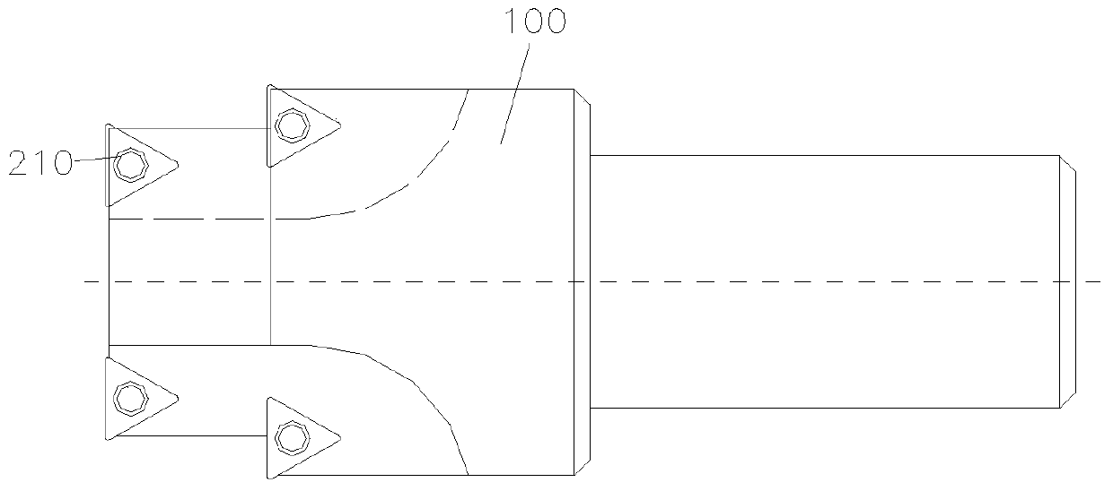
[0088] figure 1 It is a schematic structural diagram of an embodiment of an indexable tool, which includes a tool body 100 on which a number of indexable blades 210 are arranged to perform cutting processing on an object to be cut. After the edge of the edge is blunted, by turning the blade 210, other intact e...


PUM


Abstract

A manufacturing method for a cutting tool. First, a cutting area used for receiving a cutting part is provided on a blade body; then, one or more workpieces are provided and fixed at the cutting area; after that, the outer edges of the workpieces are processed to form an extrusion acting part (350). With this manufacturing method, the prefabricated workpieces (blade blanks) having two or more assembly sites are fixed at the cutting area on the cutting tool to serve as cutting parts, which then form the extrusion acting parts either directly or after slight machining, thus implementing inexpensive and rapid production and manufacturing of a molding machine machining cutting tool, and at the same time implementing replaceable blades for the molding machine machining cutting tool.

Description

technical field [0001] The invention relates to a manufacturing method of a tool, in particular to a manufacturing method of a cutting tool, so as to improve the manufacturing efficiency of the cutting tool. Background technique [0002] A cutting tool is a tool used for cutting in mechanical manufacturing, also known as a cutting tool. Since the vast majority of cutting tools are machine-used and basically used to cut metal materials, the term "knife" is generally understood as a metal cutting tool. However, with the development of material science, various materials have been widely used in the production and processing of products, such as engineering plastics and carbon fiber composite materials (CN203401118U). The tools can be divided into several types according to the form of the workpiece processing surface: tools for processing various outer surfaces, hole processing tools, thread processing tools, gear processing tools and cutting tools. [0003] The structure of...

Claims


Application Information

Patent Timeline
Patent Type & Authority Patents(China)
IPC IPC(8): B23B27/00B23P15/28
CPCB23B27/02
Inventor 不公告发明人
Owner SHANGHAI JINGREN LASER TECH
Learn More