Processing device for air inlet cylinder cover

A technology for air intake cylinder heads and processing devices, applied in metal processing equipment, devices for coating liquid on the surface, manufacturing tools, etc., can solve the problems of low efficiency of painting equipment, reduced processing quality, low processing efficiency, etc., and achieve improved grinding Work efficiency and processing quality, improvement of painting efficiency and uniformity, effect of improving painting efficiency

Inactive Publication Date: 2016-12-07
宿州市明兴金属制造有限公司
View PDF9 Cites 4 Cited by
  • Summary
  • Abstract
  • Description
  • Claims
  • Application Information

AI Technical Summary

Problems solved by technology

[0003] Grinding is usually done with a sander. Most of the current sanders have two rotating wheels with abrasive belts on them. The abrasive belts rotate continuously, and then the parts that need to be polished are placed on the abrasive belts for grinding. The size of the intake cylinder head is small, and the processing personnel generally use a hand-held method to contact and polish the intake cylinder head with the abrasive belt. This method is not only time-consuming and labor-intensive, but the processing efficiency is low, and the contact force deviation is large, and the grinding is uneven. Reduced processing quality;
[0004] After the intake cylinder head is formed and polished, it needs to be painted to achieve protection and beauty. The efficiency of the existing painting equipment is relatively low. Usually, workers spray paint on a single workpiece, and the painting is easy to pollute the environment during operation, and it is also harmful to the human body. Therefore, it is particularly important to solve such problems

Method used


Image

  • Processing device for air inlet cylinder cover
  • Processing device for air inlet cylinder cover
  • Processing device for air inlet cylinder cover

Examples


Embodiment Construction

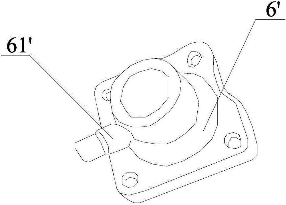
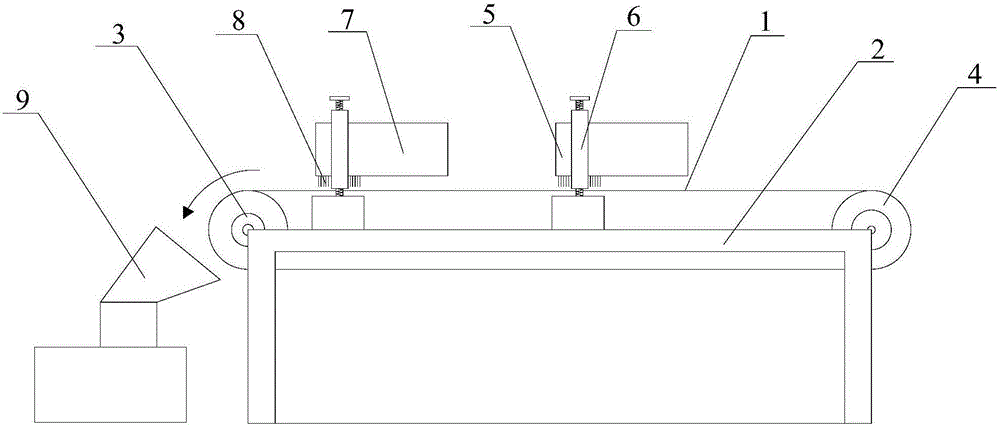
[0026] Such as Figure 2-7 As shown, the intake cylinder head processing device includes an automatic sanding machine device and a paint spraying machine connected in sequence, for processing such as figure 1 The surface of the shown air intake cylinder head 6' is polished and painted. The automatic sander device includes an abrasive belt 1, a frame 2, a driving wheel 3 and a driven wheel 4 cooperating with the driving wheel 3. The driving wheel 3 and The driven wheel 4 is horizontally arranged on the frame 2, the abrasive belt 1 is wrapped around the outer edge of the driving wheel 3 and the driven wheel 4, and two sets of retaining plates 5 are horizontally arranged above the abrasive belt 1, so that The two ends of the material blocking plate 5 are fixed on the frame 2 on both sides of the abrasive belt 1 through telescopic brackets 6, and there is a gap between the bottom end of the material blocking plate 5 and the upper surface of the abrasive belt 1.

[0027] In order ...


PUM


Abstract

The invention discloses a processing device for an air inlet cylinder cover. The processing device comprises an automatic sand grinding machine device and a paint spraying device which are sequentially joined to each other, wherein the automatic sand grinding machine device is composed of an abrasive belt, a rack, a driving wheel and a driven wheel; the driving wheel and the driven wheel are horizontally arranged on the rack; the abrasive belt wraps the outer edges of the driving wheel and the driven wheel; material stopping plates are transversely arranged above the abrasive belt; the two ends of each material stopping plate are fixed to the rack on the two sides of the abrasive belt; an interval is left between the bottom end of each material stopping plate and the upper surface of the abrasive belt; the paint spraying device is composed of a bracket; a transportation sliding rail is arranged at the upper end of the bracket and is provided with a moving lifting hook; a frame-shaped hanger is arranged at the bottom of the moving lifting hook and is provided with bolt holes; the bolt holes are fit to gas transmission pipes of the air inlet cylinder cover to enable the air inlet cylinder cover to sleeve the bolt holes; the transportation sliding rail penetrates through a paint spraying chamber; a paint spraying machine is arranged in the paint spraying chamber and is provided with an infrared sensor; and a drying device is arranged at the back end of the paint spraying chamber.

Description

technical field [0001] The invention relates to the technical field of cylinder head processing, in particular to an intake cylinder head processing device. Background technique [0002] In the production of piston cylinder intake cylinder head (such as figure 1 (shown) parts, most of them are molded by hydraulic casting of molten aluminum with a die-casting machine. After the die-casting is completed, the product needs to be taken out, deburred, and then further polished to ensure that the surface of the product is smooth and smooth. [0003] Grinding is usually done with a sander. Most of the current sanders have two rotating wheels with abrasive belts on them. The abrasive belts rotate continuously, and then the parts that need to be polished are placed on the abrasive belts for grinding. The size of the intake cylinder head is small, and the processing personnel generally use a hand-held method to contact and polish the intake cylinder head with the abrasive belt. This ...

Claims


Application Information

Patent Timeline
Patent Type & Authority Applications(China)
IPC IPC(8): B24B21/00B24B41/00B05C5/00B05D3/02
CPCB05C5/00B05D3/0263B24B21/00B24B41/00
Inventor 雷怀明
Owner 宿州市明兴金属制造有限公司
Why Eureka
Try Eureka