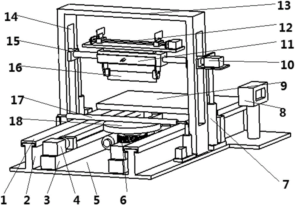
Sponge cutting machine fulfilling various cutting functions

A sponge cutting machine, functional technology, applied in the direction of metal processing, etc., can solve the problems of high cost, low work efficiency, low profit, etc., and achieve the effect of meeting processing needs, strong practicability, and simple structure

Inactive Publication Date: 2016-12-07
TIANJIN XINYIDA FURNITURE CO LTD
View PDF0 Cites 15 Cited by
  • Summary
  • Abstract
  • Description
  • Claims
  • Application Information

AI Technical Summary

Problems solved by technology

[0002] The sponge cutting machine is used to cut larger pieces of sponge. Since such large pieces cannot be cut if they are cut purely by hand, it takes a lot of manpower and material resources, and the efficiency is low, which cannot adapt to mass production. Therefore, sponge cutting Machines emerged as the times require. The existing sponge machines are divided into manual sponge cutting machines and CNC sponge cutting machines. Although the manual cutting machines are cheap, they still need to be manually operated during the processing process, which increases the workload of the staff and the relative work efficiency. Low, in a large competitive environment, the profits obtained by enterprises are low, and it is not suitable for cutting and processing a large number of sponges. The CNC cutting machines commonly used in the market generally use laser cutting. Although the cutting efficiency is high and the incision is relatively flat, but This kind of equipment is expensive, and can only cut one type of large sponge flatly. If the company invests in a piece of equipment for production, it will not be able to recover the cost for a long period of time, so the company prefers I tend to use the automatic cutting machine with common cutting methods, so I designed an automatic cutting machine that meets the actual production needs of my company. After searching the relevant patent documents, no sponge cutting ...

Method used


Image

  • Sponge cutting machine fulfilling various cutting functions
  • Sponge cutting machine fulfilling various cutting functions
  • Sponge cutting machine fulfilling various cutting functions

Examples


Embodiment Construction

[0036] It should be noted that the embodiments of the present invention and the features of the embodiments may be combined with each other under the condition of no conflict.

[0037] In the description of the present invention, it should be understood that the terms "center", "portrait", "horizontal", "top", "bottom", "front", "rear", "left", "right", " The orientation or positional relationship indicated by vertical, horizontal, top, bottom, inner, outer, etc. is based on the orientation or positional relationship shown in the drawings, and is only for the convenience of describing the present invention and The description is simplified rather than indicating or implying that the device or element referred to must have a particular orientation, be constructed and operate in a particular orientation, and therefore should not be construed as limiting the invention. In addition, the terms "first", "second", etc. are used for descriptive purposes only, and should not be constru...


PUM


Abstract

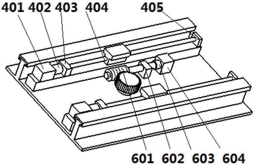
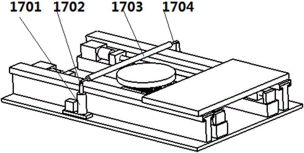
The invention provides a sponge cutting machine with multiple cutting functions, which includes a base, a guide rail and a slide block are arranged on the base, a first workbench is fixed on the slide block, and a linear movement is provided between the first workbench and the base mechanism, the base is provided with a second workbench, a rotating mechanism is provided between the second workbench and the base, and a bracket is provided on the base, and vertical square grooves are opened on both sides of the bracket, and the square grooves are equipped with The guide block is provided with a first lifting mechanism on both sides of the base close to the support, passing through the two guide blocks through the first drive mechanism and rotatingly connected with a tool holder, and the tool holder is respectively provided with a first cutting device and a second cutting device. device and the third cutting device, the base is additionally provided with a control unit. A sponge cutting machine that realizes multiple cutting functions described in the present invention has a simple structure and is easy to operate, and can meet the needs of various cutting methods for large sponges on one piece of equipment, and has high cutting efficiency, which brings great benefits to enterprises. to higher earnings.

Description

technical field [0001] The invention belongs to the field of sponge processing equipment, in particular to a sponge cutting machine that realizes multiple cutting functions. Background technique [0002] The sponge cutting machine is used to cut larger pieces of sponge. Because such large pieces cannot be cut, if the cutting is done purely by hand, it will take a lot of manpower and material resources, and the efficiency is low, which cannot be adapted to mass production. Therefore, sponge cutting The existing sponge machine is divided into manual sponge cutting machine and CNC sponge cutting machine. Although the manual cutting machine is cheap, it still needs manual operation in the processing process, which increases the workload of the staff and the relative work efficiency. Low, in a large competitive environment, the profit obtained by the enterprise is low, and it is not suitable for cutting a large number of sponges. The CNC cutting machine commonly used in the marke...

Claims


Application Information

Patent Timeline
IPC IPC(8): B26D9/00B26D7/20B26D7/26B26D7/00B26D5/08B26D5/02
CPCB26D9/00B26D1/0006B26D5/02B26D5/08B26D7/00B26D7/20B26D7/2614B26D7/2628B26D2001/006
Inventor 冯天军
Owner TIANJIN XINYIDA FURNITURE CO LTD
Why Eureka
Try Eureka