A plastic film extruder

A technology of plastic film and extruder, applied in the field of machinery, can solve the problems of difficulty in assembling the device, and achieve the effects of improving the convenience of assembly, improving the convenience and reducing the use.

Active Publication Date: 2019-03-26
ZHEJIANG SHANGCHENG SCI&TECH
View PDF12 Cites 1 Cited by
  • Summary
  • Abstract
  • Description
  • Claims
  • Application Information

AI Technical Summary

Problems solved by technology

[0004] There is a problem with the above-mentioned device: the pumping chamber is directly connected to the inner cavity of the extrusion cylinder through the through hole, and there is no auxiliary structure in between, which makes the assembly of the whole device difficult

Method used


Image

  • A plastic film extruder
  • A plastic film extruder
  • A plastic film extruder

Examples


Embodiment 1

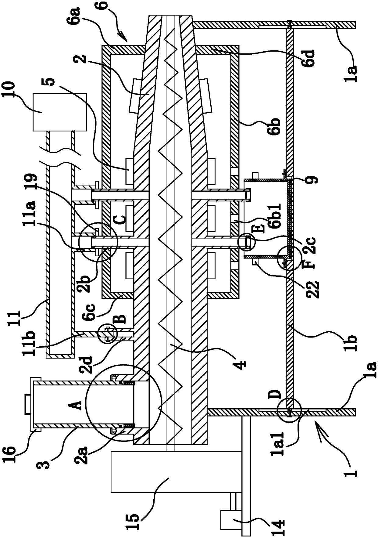
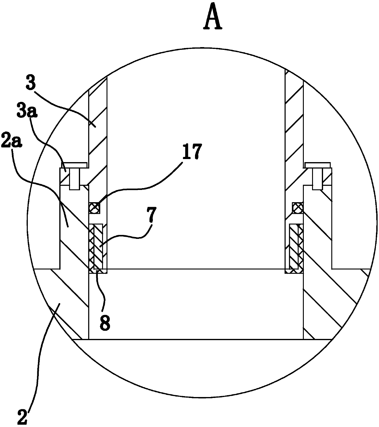
[0065] Such as Figure 1 to Figure 8 As shown, the plastic film extruder consists of a frame 1, an extrusion barrel 2, a feeding barrel 3, a feeding screw 4, an electric heater 5, a heat insulating barrel 6, a magnetic block 7, a protective cover 8, a water storage tank 9, Air suction pump 10, air extraction pipe 11, dustproof net 12, pressure cap 13 etc. are formed. Wherein, the heat insulation cylinder 6 and the protective cover 8 are all made of thermal insulation materials, such as thermal insulation rock wool, molded polystyrene board, extruded polystyrene board, etc.; the feeding cylinder 3 and the water storage tank 9 are made of magnetic Material, the magnetic material can be iron or iron alloy.

[0066] Specifically, as figure 1 with Figure 5 As shown, the frame 1 is I-shaped, and the frame 1 includes two connecting plates 1a arranged vertically and a supporting plate 1b between the two connecting plates 1a. Wherein, the two ends of the support plate 1b are fixed...

Embodiment 2

[0082] The structure and principle of this second embodiment are basically the same as that of the first embodiment, except that: the lower end surface of the annular retaining shoulder 3a is provided with an annular sealing groove, and an annular gasket is arranged in the sealing groove, and the annular seal Both end surfaces of the pad abut against the bottom wall of the sealing groove and the end surfaces of the connecting portion 2a, respectively. Under the action of the annular gasket, a reliable seal is formed between the annular shoulder 3a and the connecting portion 2a, so that the purpose of sealing and fixing the feeding cylinder 3 and the connecting portion 2a is stably achieved.

Embodiment 3

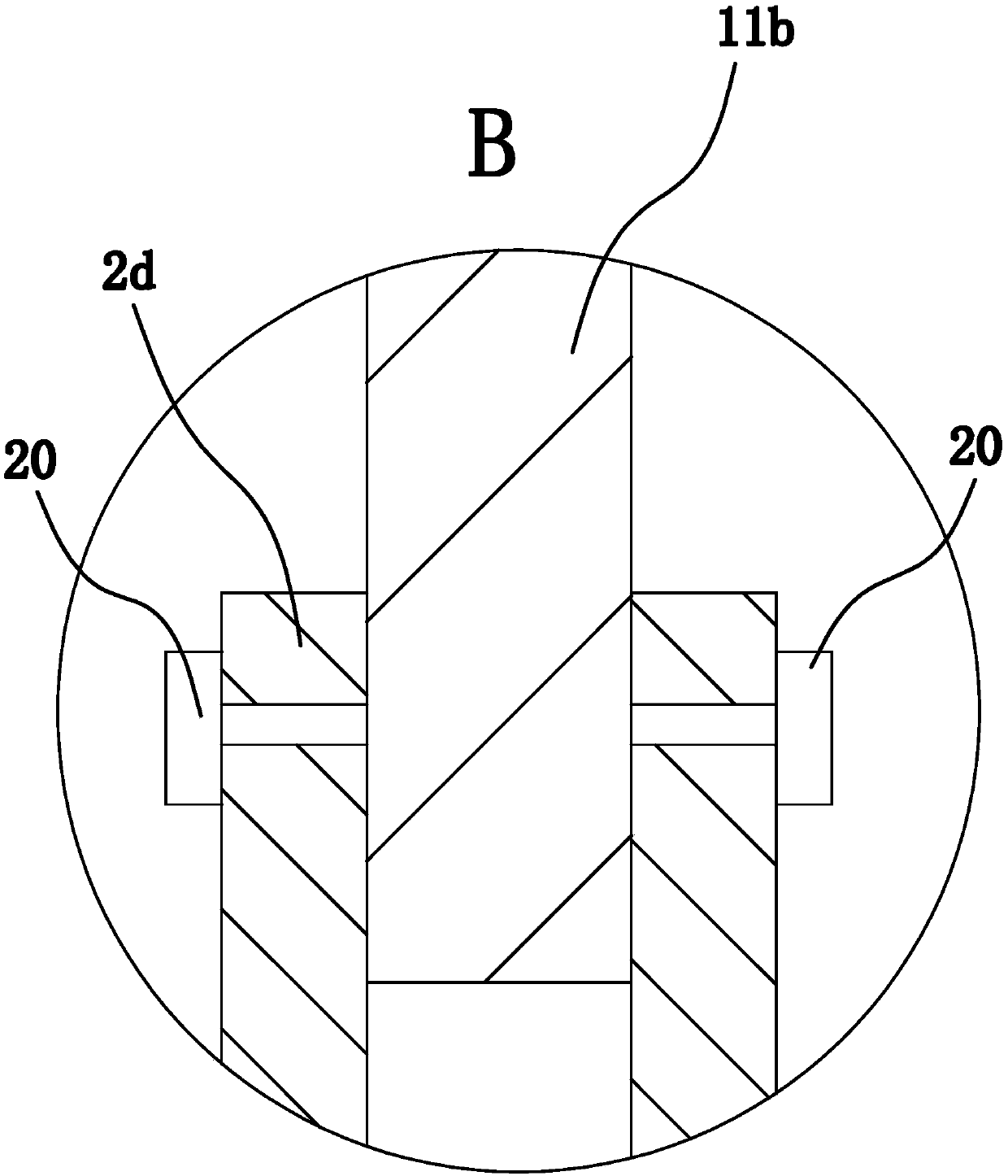
[0084] The structure and principle of the third embodiment are basically the same as those of the first embodiment, except that the locking mechanism includes the second threaded hole penetrating through the side wall of the positioning part 2d, the third threaded hole provided on the side wall of the sliding part 11b and There are several bolts 2 and 3 threaded in the threaded hole 2 and they are distributed along the axial direction of the sliding part 11 b . The end of the bolt 2 is threaded in one of the threaded holes 3 .


PUM


Abstract

The invention provides a plastic film extruding machine and belongs to the technical field of machines. The plastic film extruding machine solves the problem that an existing extruder is inconvenient to assemble. The plastic film extruding machine comprises a machine frame and an extruding cylinder arranged on the machine frame. A feeding screw is arranged in the extruding cylinder. A driving mechanism capable of driving the feeding screw to rotate is arranged on the machine frame. A feeding cylinder is arranged above the extruding cylinder. Electric heaters are fixed to the outer side walls of the middle portion and the right end of the extruding cylinder. An inner cavity of the feeding cylinder communicates with the inner cavity of the extruding cylinder. The extruding cylinder is sleeved with a thermal insulation cylinder. The electric heaters are both located in the thermal insulation cylinder. The upper side wall and the lower side wall of the middle portion of the extruding cylinder are provided with a cylindrical exhaust portion and a cylindrical drainage portion correspondingly. The thermal insulation cylinder is formed by splicing an upper shell body and a lower shell body, wherein the longitudinal sections of the upper shell body and the lower shell body are both semicircular. The upper shell body is provided with a first through connecting hole. The lower shell body is provided with a second through connecting hole. The exhaust portion is fixedly inserted into the first connecting hole in a close fit manner. The drainage portion is fixedly inserted into the second connecting hole in a close fit manner. The plastic film extruding machine has the advantage of being convenient to assemble.

Description

technical field [0001] The invention belongs to the technical field of machinery, and relates to an extruder, in particular to a plastic film extruder. Background technique [0002] Plastic film is the raw material for making woven bags. The production process is as follows: dry the mixed raw materials and put them into the hopper of the extruder. With the rotation of the feeding screw, the raw materials are forced to the die head. Small, the raw material is continuously compacted during the forward process, the gas is discharged, and at the same time it is squeezed, sheared, the temperature is raised, and the heat source of the heater is absorbed, so that the temperature of the raw material is gradually increased and undergoes a three-state transition, that is, it is gradually transformed from the glass The state becomes a highly elastic state, and finally becomes a viscous flow state, reaching complete plasticization, and extruding the film from the die. [0003] Existing...

Claims


Application Information

Patent Timeline
Patent Type & Authority Patents(China)
IPC IPC(8): B29C48/76B29C48/80B29C48/96B29C48/285B08B17/00
CPCB08B17/00B29C48/285B29C48/761B29C48/767B29C48/78B29C48/96
Inventor 张伟忠苏跃锋施叶标汪琴伟
Owner ZHEJIANG SHANGCHENG SCI&TECH
Why Eureka
Try Eureka