A kind of self-steering bogie and self-steering method of railway freight car

A technology for railway freight cars and bogies is applied in the field of three-piece self-steering bogie self-steering methods and bogies, which can solve the problem of increasing the fixed wheelbase of the bogie and the center distance of the axle diameter, increasing the manufacturing and operating costs, and increasing the installation cost. and inconvenient disassembly, to achieve the effect of increasing manufacturing costs, facilitating installation and maintenance, and reducing manufacturing and maintenance costs

Active Publication Date: 2021-01-26
株洲市求拙机械制造有限公司
View PDF10 Cites 0 Cited by
  • Summary
  • Abstract
  • Description
  • Claims
  • Application Information

AI Technical Summary

Problems solved by technology

[0004] However, the main disadvantage of the traditional wheel set self-guiding device is that the sub-frame is arranged between the wheel and the side frame and between the wheel and the bolster. Compared with the standard bogie, there are the following disadvantages:
[0005] 1) The sub-frame is located between the rubber spring cap of the side frame and the chute of the brake beam in the vertical plane, so it is extremely inconvenient to install and disassemble
[0006] 2) Increase the fixed wheelbase of the bogie and the center distance of the shaft diameter, which increases the weight of the bogie and increases the manufacturing and operating costs
[0007] 3) The auxiliary frame is located outside the brake shoe support, which makes it difficult to replace the brake shoe and increases maintenance costs
[0008] 4) The sub-frame is located on the side of the wheel set close to the center of the bogie, which makes the layout of the foundation braking device, especially the braking device installed on the bogie, difficult and affects its application
[0013] Although the above-mentioned patents all relate to the self-guiding device of the railway freight car bogie, and have also proposed some structural improvements, they have not fundamentally changed the existing self-guiding principle, and there are still several aspects mentioned above. Insufficient, so there is still room for further improvement

Method used


Image

  • A kind of self-steering bogie and self-steering method of railway freight car
  • A kind of self-steering bogie and self-steering method of railway freight car

Examples


Embodiment 1

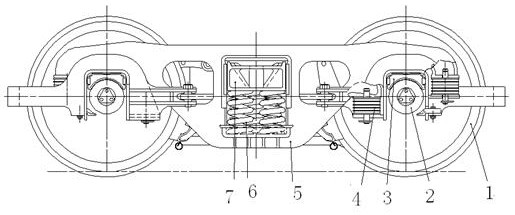
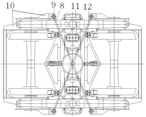
[0032] by attaching figure 1 with 2 It can be seen that the present invention relates to a self-guiding device for a railway freight car bogie, comprising: a wheel set 1, a rolling bearing device 2, a bearing saddle 3, a series of rubber springs 4, side frames 5, a central spring damping device 6, and a bolster 7. Connecting rod 8, connecting pin 9, subframe 10, side bearing 11, braking device 12, side frame 5 is pressed on the wheel pair 1 through subframe 10.

[0033] Such as figure 2 As shown, two sub-frames 10 are arranged at both ends of the bogie, the coupling pin 9 is located outside the side frame, and the connecting rod 8 passes through the holes reserved in the abdomen of the side frame 5 and the bolster 7 . The two sub-frames 10 and the two connecting rods 8 are cross-connected through four connecting pins 9 to form the guiding device of the bogie wheel set. When the bogie passes through the curve, the guiding force applied by the rail to the wheel, through the ...

Embodiment 2

[0035]The structure of the second embodiment is the same as the basic principle of the first embodiment, but the arrangement of the connecting rods is different, as shown in the attached figure 2 shown. The side frames are connected by bolsters, and the two sub-frames are connected by connecting rods, so that the left and right wheels of the vehicle are integrated to form a self-guiding device; the principle of rolling the arc-shaped barrel is used to make the wheel diameter in contact with the rail Continuously changing, thus realizing the automatic rotation rolling guide.

[0036] The two sub-frames are connected by connecting rods by bypassing the two ends of the bogie; and the connection points between the two sub-frames and the connecting rods are located outside the side frame (that is, away from the longitudinal centerline side of the track) , so that when the bogie passes through the curve, the guiding force applied by the rail to the wheel tends to the radial positi...


PUM


Abstract

The invention relates to an automatic-directing bogie of a railway truck and an automatic-directing method. The automatic-directing bogie comprises a wheel pair, a rolling bearing device, a load bearing saddle, a shaft tank rubber spring, a side frame, a swing bolster, a spring damping device, a basic braking device and automatic-directing devices. The automatic-directing bogie is characterized in that two secondary frameworks of the automatic-directing device of the bogie are arranged at the outer ends of the bogie, and connecting points of the two secondary frameworks and a corresponding cross rod are located on two sides of the bogie. According to the automatic-directing bogie disclosed by the invention, the two secondary frameworks on the outer side of the side frame are in hinge connection with the cross connecting rods, so that under the situation that the total arrangement of a conventional bogie is not changed, the automatic-directing of the bogie can be realized, so that the structure of the secondary frameworks is simplified, mounting and overhauling are facilitated, and a central distance of the shaft diameter of the bogie is reduced; mounting the basic braking device of the bogie, particularly a unit type braking device is facilitated, so that the purposes that manufacturing cost and maintaining cost are greatly reduced, the manufacturing of the bogie is improved and the technological properties are maintained are achieved.

Description

technical field [0001] The invention relates to a walking method and device for railway freight cars, in particular to a self-guiding method and a bogie for a railway freight car bogie, in particular to a self-guiding method and a bogie for a three-piece self-guiding bogie. The utility model is mainly used for steering traction in the running process of railway freight cars, and belongs to the technical field of railway freight car manufacturing. Background technique: [0002] With the increase of the running speed of the freight car, in order to maintain its fast running stability, the traditional freight car bogie usually adopts a large horizontal connection stiffness between the wheel set and the side frame, but this limits the improvement of its curve passing performance. Conventional steering The frame cannot meet the requirements of both curve passing performance and lateral stability at the same time. In order to effectively solve this contradiction, it can not only ...

Claims


Application Information

Patent Timeline
Patent Type & Authority Patents(China)
IPC IPC(8): B61F5/38
CPCB61F5/38
Inventor 李国宫万禄淡赵军
Owner 株洲市求拙机械制造有限公司
Why Eureka
Try Eureka