Purification system for removing oil by carbon sponge
A technology of purification system and carbon sponge, which is applied in the field of purification system using carbon sponge to remove oil, can solve the problems of large water consumption and waste of water resources, and achieve the effects of simple operation, cost saving and remarkable effect
- Summary
- Abstract
- Description
- Claims
- Application Information
AI Technical Summary
Problems solved by technology
Method used
Image
Examples
Embodiment 1
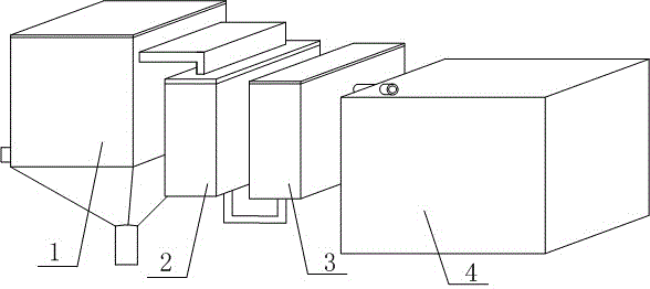
[0027] Degreasing systems with carbon sponges, such as figure 1 As shown, it includes a water storage tank 1 with a tapered bottom end, a water inlet arranged at the middle part of the water storage tank 1, a water outlet arranged at the top of the water storage tank 1, and a slag outlet arranged at the bottom end of the water storage tank 1; the water storage tank The water outlet of 1 is connected with desilter tank 2, degreasing tank 3 and biological purification tank 4 in sequence.
[0028] The degreasing tank 3 includes a tank body and a carbon sponge arranged in the tank body.
Embodiment 2
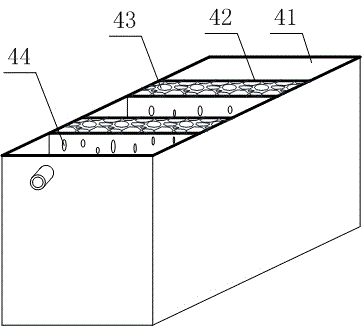
[0030] The difference between this embodiment and Embodiment 1 is that the structure of biological purification tank 4 is optimized in this embodiment, such as image 3 As shown, the specific settings in this embodiment are as follows:
[0031] The biological purification tank 4 comprises a purification tank 41, a biological planting pool 42 arranged in the purification pool 41, a stone 43 arranged in the biological planting pool 42; the wall of the biological planting pool 42 is provided with a seepage port 44 .
[0032] Described biological planting pool 42 is square and is more than two, is arranged side by side in purification pool 41 and this purification pool 41 is divided into more than three areas, by planting aquatic purification plant on the stone 43 of biological planting pool 42 It can effectively beautify the environment and effectively achieve the purpose of purifying water quality.
Embodiment 3
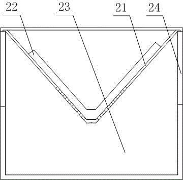
[0034] The difference between this embodiment and embodiment 1 or embodiment 2 is that the structure of desilter tank 2 is optimized in this embodiment, such as figure 2 As shown, the specific settings in this embodiment are as follows:
[0035] The desilting tank 2 includes more than two seepage tanks 21 whose bottom ends are V-shaped and arranged in parallel, a sponge body 22 arranged inside the seepage tank 21, and a collection tank 23 arranged at the bottom end of the seepage tank 21; the sponge body The seepage groove 21 below 22 is provided with the through hole that is used for water flow to pass through;
[0036] The top of the seepage tank 21 is located below the water outlet of the water storage tank 1 .
[0037] The sponge body 22 is detachably connected to the seepage tank 21 . The desilter tank 2 also includes a housing 24 , the water seepage tank 21 is hooked on the top of the housing 24 , and the collection tank 23 is fixed on the housing 24 below the water s...
PUM
 Abstract
Description
Claims
Application Information
 - R&D
- Intellectual Property
- Life Sciences
- Materials
- Tech Scout
- Unparalleled Data Quality
- Higher Quality Content
- 60% Fewer Hallucinations
Browse by: Latest US Patents, China's latest patents, Technical Efficacy Thesaurus, Application Domain, Technology Topic, Popular Technical Reports.
© 2025 PatSnap. All rights reserved.Legal|Privacy policy|Modern Slavery Act Transparency Statement|Sitemap|About US| Contact US: help@patsnap.com


